Design, CFD Validation and Manufacture of a Race Cars Fuel Tank
Follow article Dave from DesignSpark
How do you feel about this article? Help us to provide better content for you.
Dave from DesignSpark
Thank you! Your feedback has been received.
Dave from DesignSpark
There was a problem submitting your feedback, please try again later.
Dave from DesignSpark
What do you think of this article?
Introduction
This project aims to design, simulate, and manufacture a new fuel tank for a Formula Student Race Car for UoL Racing.
In 2024 UoL Racing are changing fuels from E10 to the more viscous and less chemically dense E85. This combined with a host of other issues have presented the opportunity for the fuel tank to be optimised using CFD.
Objectives
The objectives of this project are to minimise the weight of the tank while also eliminating the fuel starvation issues the old fuel tank design experienced. Other objectives for this project include moving the fittings from their previously hard-to-reach places, as well as trying to keep the centre of gravity as low as possible.
Methodology
For this project, I will first be modelling the previously designed fuel tank in Solidworks 2023 and then setting up and running a simulation to study the fuel sloshing within the fuel tank to see what the cause of the fuel starvation issue is. This will be done in Siemens StarCCM+.
Once this has been established, I will move on to designing the new fuel tank in Solidworks and then I will validate my design in StarCCM+ using the same simulation.
Once this design is finalised and validated it will be manufactured and installed on the car.
Simulation Setup
The simulation will be set up within Siemens StarCCM+ 2023.
The simulation uses the K-Epsilon turbulence model, Volume of Fluid (VOF) and Multiphase Interaction within StarCCM+. It also is an implicit unsteady simulation.
To model the interaction between the phases present in the tank I have used the Eulerian Multiphase physics model. Within the Eulerian Multiphases section of this simulation, two phases are set up. Inside these two phases, the following models are applied.
- Constant Density
- Liquid/Gas
- Turbulent
This is where I have applied the properties of both the fuel and air. This will be the part I change when I simulate the tank with E85 inside.
The success of the simulation will be decided by plotting the amount of fuel present at the fuel pump’s pickup. This will allow me to highlight the elimination of the fuel starvation issue which the 2023 tank had.
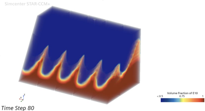
Above is the output of the simulation showing the previous tank design and how the internals of the tank work to try and prevent the fuel starvation issues.
Product
Thanks to RS who have chosen to fund this project I will be purchasing the fittings required for the tank, some of the adhesives I plan on using in certain areas, along with the tools I will need to finish this project.
Next Steps
The next steps for this project are the concept selection for the new fuel tank design followed by the CFD validation. Once this lengthy process is done, I will begin the manufacture of the components required.
Another big thank you to RS who have chosen to support my project by awarding me a spot on the RS Student Project Fund.
Find me on LinkedIn here: www.linkedin.com/in/dylanccrawford
Comments