mini Mini-Make
Follow project
 Dave from DesignSpark
How do you feel about this article? Help us to provide better content for you.
Dave from DesignSpark
Thank you! Your feedback has been received.
Dave from DesignSpark
There was a problem submitting your feedback, please try again later.
Dave from DesignSpark
What do you think of this article?
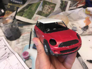
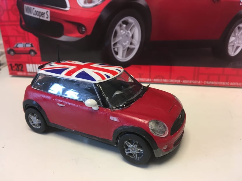
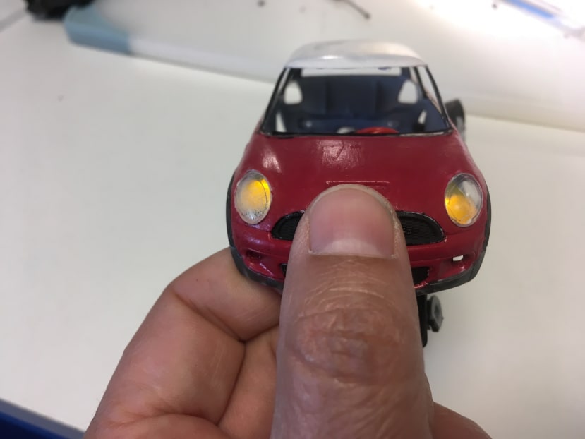
 Modded Mini Cooper - to become a nightlight - its headlights automatically come on when it is dark.
Parts list
| Qty | Product | Part number | |
|---|---|---|---|
| 2 | 2 yellow casing LEDs | ||
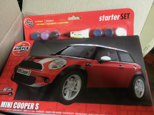
| 1 | Mini Cooper S 1:32 Scale Gift Set | ||
| 1 | Light dependent resistor | ||
| 1 | 330R resistor | ||
| 1 | 1KR resistor | ||
| 1 | CR2032 Battery Case | ||
| 1 | CR2032 Battery | ||
| 1 | Transistor | ||
What better mini-make than to make a Mini! I wanted to hack an Airfix Mini Cooper and make it into a night-light - with the headlights coming on automatically.
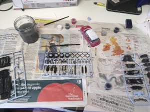
I've never made an Airfix model (I think my parents knew my patience level as a child). So I chose the easiest skill level and a starter set - which I thought included everything I needed paint, cement and paintbrushes:
I read the instructions (yes, I do that).
Here are the things I wished it had said or wished I knew before I started:
- Prime all the parts first. Priming was not mentioned on the included instruction sheet. I can understand the kit is sold for 8-year-olds, and primer and 8-year-olds don't always mix well. But a comment about it would have been good.
- Acrylic paints are often best used watered down - use a palette (e.g. margarine tub lid) to mix the water and paint.
- Use wet and dry sandpaper to rub down the paint between coats.
- If the instructions indicate that a lot of items are cemented together AND are the same colour, cement first, then paint them together.
- Push fit the parts before you get the glue out.
- The project will take longer than you imagine.
Other bonus ideas:
- Use an airbrush or spray paints for large blocks of colour
- Get a lot of swear words ready for the application of transfers
- There are a lot of hints and tips at https://www.airfix.com/uk-en/support/tips/
- Varnish the finished product to protect it.
But because I didn't know those things I started as per the instructions ...
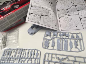
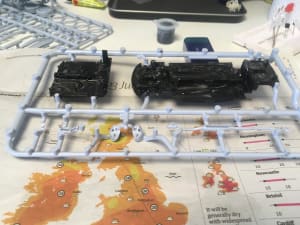
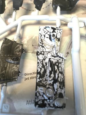
The first dilemma - paint on the sprue (the channels which the plastic is poured into the mould or assemble first - I chose to paint on the sprue due to the fiddly-ness of the parts.
I was very disappointed with my first attempts.
Paint too thick:
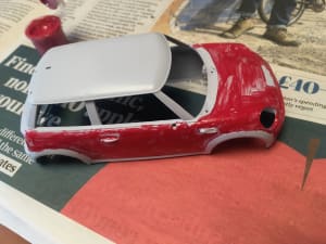
Lack of primer:
So I rubbed down with wet and dry and tried again:
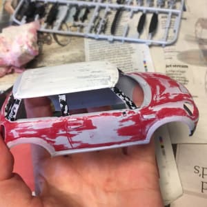
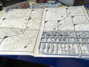
There were a LOT of parts. And most needed a few coats (due to me not using a primer!). The painting process took me 12 days. Yes, TWELVE. OK, sometimes I only did 5 mins a day. But 12?!!
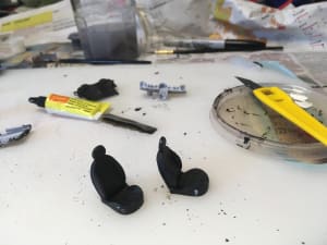
Eventually, it was assembly time ...
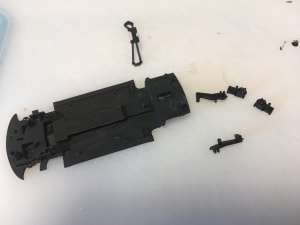
I needed to scrape a lot of the paint off so that it would stick.
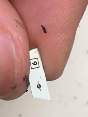
Applying transfers is a skill set all of its own - and may require a magnifying glass:
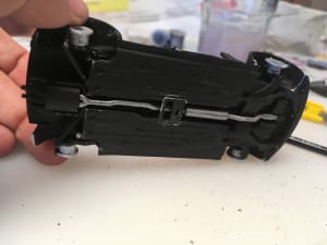
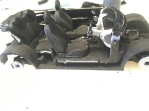
Because I wasn't sure how much space I would have inside for batteries, I made up most of the model before starting the electronics. I eventually realised there was hardly any space, so I decided on a CR2032 3V button cell battery stuck on the bottom of the car.
Underneath:
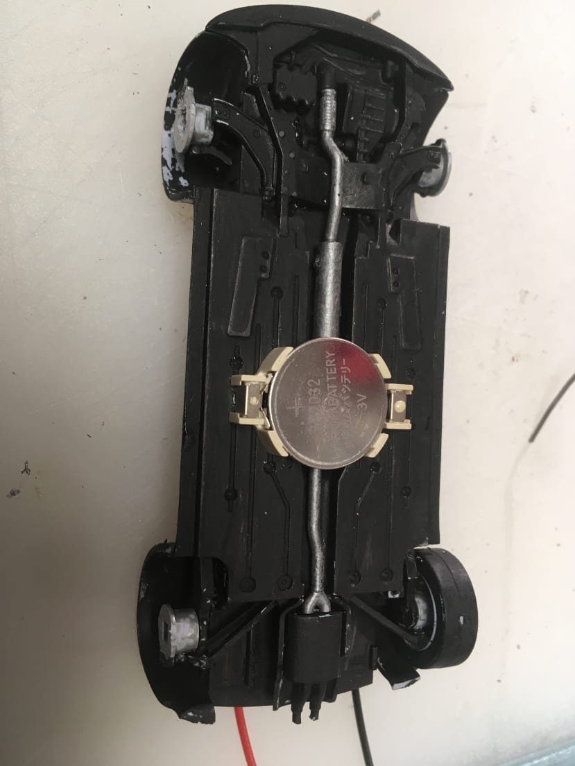
Wires through the body:

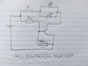
Once I knew which battery I was using, I could make up the circuit ...
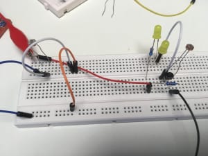
Note to self: When your circuit does not work as expected, check that you have used a 330-ohm resistor, and not actually a 330K ohm resistor. #LucyFail
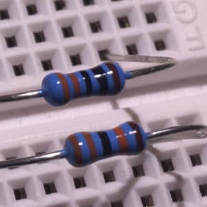
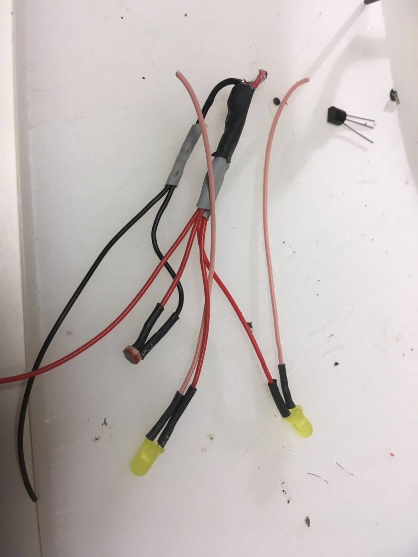
For the LEDs I used (which were random yellow ones I found in my box of electronics), and a 3V battery, R1 was 330 ohms and R2 was 1000 ohms. The Light Dependent Resistor (LDR) was also a random one found in my electronics box. The Transistor was NPN.
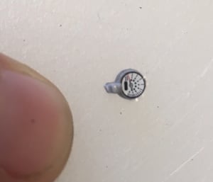
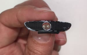
I discovered the LDR fits nicely in the grill ...
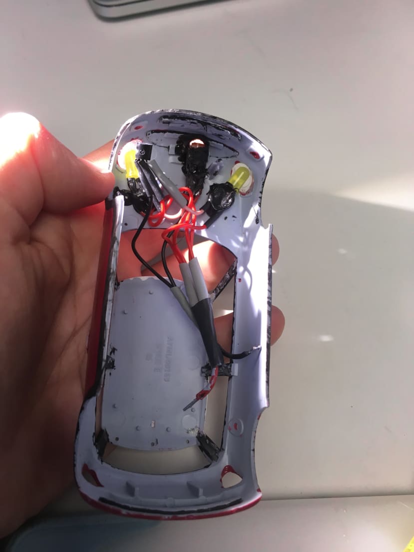
I then made the wiring loom ...
And hot melt glued it in place ...
Getting it all to fit was fun ...
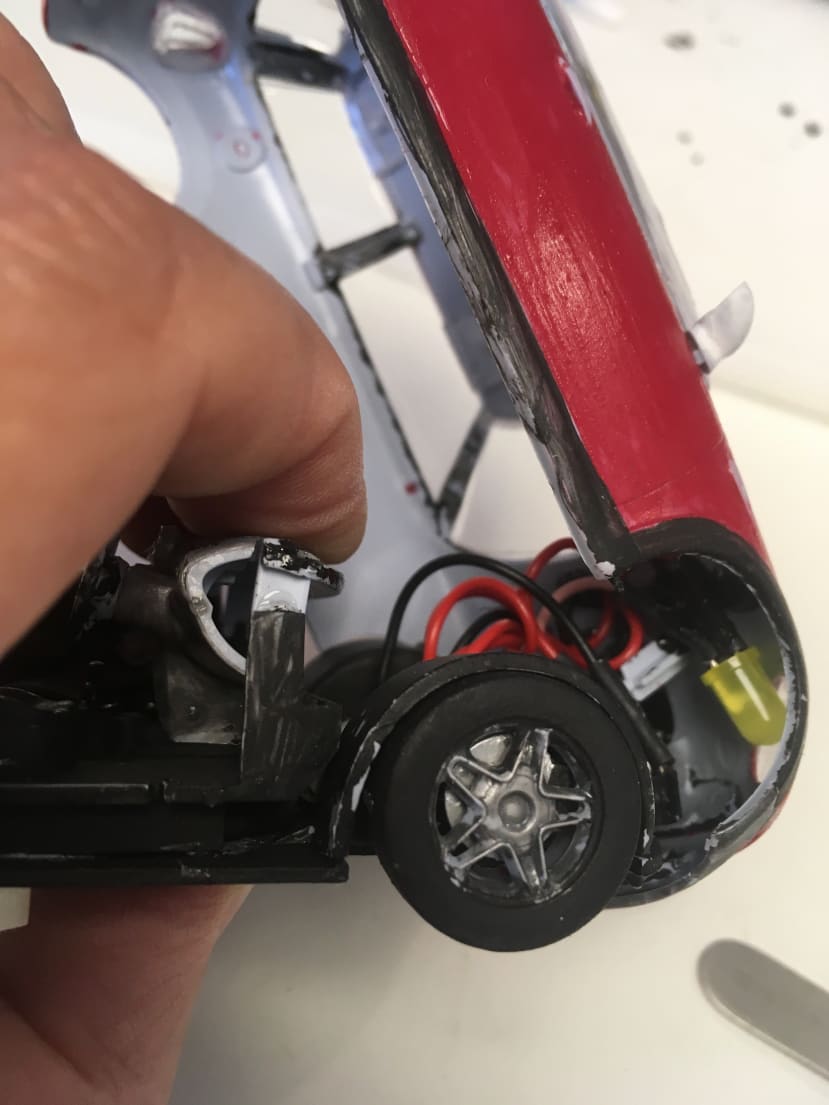
But I did it!
I then finished the build (headlight lenses, more transfers, painting more fiddly bits ...)
Comments