Home Automation (Domotic) House with Arduino
Follow project
 Dave from DesignSpark
How do you feel about this article? Help us to provide better content for you.
Dave from DesignSpark
Thank you! Your feedback has been received.
Dave from DesignSpark
There was a problem submitting your feedback, please try again later.
Dave from DesignSpark
What do you think of this article?
 Due to our purpose to divulgate new technologies and educate students around our community, we started this project of a domotic house. It was exposed to a school event which was organized to concern about the climate change and greenhouse effect.
Parts list
| Qty | Product | Part number | |
|---|---|---|---|
| 20 | 2.25 V Red LED 5mm Through Hole, Kingbright L-53HD | 228-5988 | |
| 15 | Black Button Tactile Switch, Single Pole Single Throw | 161-3779 | |
| 1 | Solar cell | ||
| 1 | Temperature and humidity sensor | Dht22 | |
| 1 | Resistencia Dependiente de Luz (LDR) Luna Optoelectronics, CdS Montaje en orificio pasante TO-18, 20 kΩ | NSL-19M51 | |
| 1 | Alps Alpine Mechanical Rotary Encoder, 24 Pulse Flat, Through Hole Mount | 172-7599 | |
| 1 | Arduino LCD display | hd44780 | |
| 2 | Arduino Uno DIP rev.3 ATmega328 - MCU AVR | 715-4081 | |
| 3 | Breadboard Prototyping Board 80 x 60 x 10mm | 102-9147 | |
| 100 | Arduino cable | ||
Project and functions
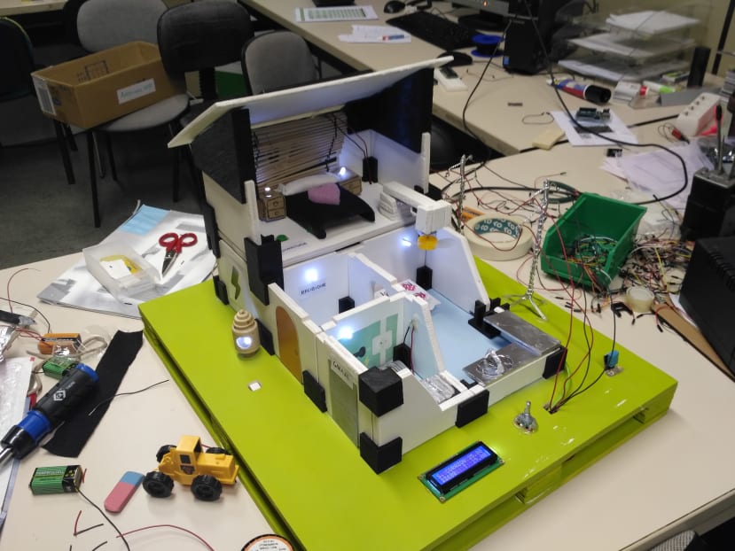
Once the objective was defined, our team members started to design the structure and functions of the building. First of all, we had to measure, cut, sand down and paint all the parts of the house: base, floor, walls, ceiling… After that, we took advantage of our 3D printer and create all joints with PLA material to have the structure ensambled.
Consequently, the electronic system with arduino was next. We used more than 20 LEDs, 15 buttons, 1 solar cell, 1 temperature and humidity sensor, 1 LDR sensor, 1 encoder, 1 LCD display, 2 arduino, 3 protoboards and a lot of conductor cables.
There were some systems to programme:
- Presence detection in each room of the house
- Passive light system depending the weather and hour of the day: night, clouds, …
- Temperature and humidity detection outside the house
- Set up an interactive clock in the LCD display
- Heating and cooling systems depending if it is winter or summer
- Electric car charge during night hours
However, all these systems were programmed in 2 arduino boards and because of that we had to struggle with a harder challenge. While one of the arduino was responsible about taking information from all sensors to visualize it in the LCD display, the other one, was defined to manage the light system working correctly. To achieve this we had to make a communication between both arduinos. This was the hardest part of the project but we got it.
Conclusion
In general terms, this project was succesful. We have shown it in several expositions for students and we are very proud about the work we have done. Maybe it could have been greater if we had had more time before the first exposition, but no problem, we can try it again.