RS IoT Blockchain Demonstrators Part 3: Electronics
Follow article
 Dave from DesignSpark
How do you feel about this article? Help us to provide better content for you.
Dave from DesignSpark
Thank you! Your feedback has been received.
Dave from DesignSpark
There was a problem submitting your feedback, please try again later.
Dave from DesignSpark
What do you think of this article?

The selection and integration of electronics for the IoT Blockchain demonstrators.
This series of posts looks at the design and build of a set of demonstrators for the bi-annual Electronica trade fair and conference, which show how blockchain technology can be used to create a secure, decentralised data platform and more for the Internet of Things.
In this post, we take a look at the electronic components used.
Robust, aesthetically pleasing and user-friendly
As my colleague, Dave Ives, mentioned in part 2 when covering the mechanical build, the demonstrators needed to look good and be robust enough to transport to Electronica — and no doubt to and from other future events also. In addition, they had to be user-friendly, both for visitors and the staff who would be operating the demonstrators. As such it was important to think about the type, size and placement of controls, with an overall design that makes for fuss-free operation.
Rear panel
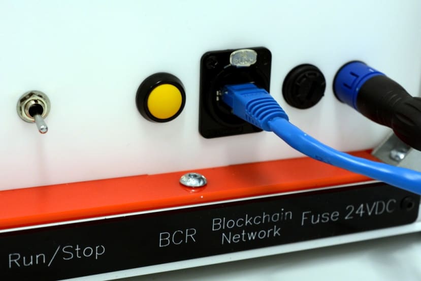
With the above in mind the rear panel on each of the units features the same layout and has:
-
Power in via Binder 720 Series connector (734-5571)
-
Fuse holder (512-5996)
-
Ethernet connection (909-3714)
-
BCR momentary yellow button (040-8050)
-
Reboot momentary red button (864-4462)
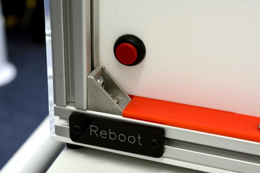
The reboot button is purposely placed close to one side, so as to provide easier access. Whilst the button labelled BCR — which triggers a blockchain data reset — is placed close to the centre.
Although an IP67 rating is not necessary given the environment, Binder 720 series connectors were selected for DC power input, since these have a very positive locking action, unlike, for example, a simple DC coaxial/barrel connector. They also have the added bonus of being available in a variety of colours and pin configurations, which meant that different ones could be used for different power supply ratings, greatly reducing the potential for failure resulting from using the incorrect PSU.
In the first of the two images above we can also see a switch labelled run/stop, which is only present on the Machine Failure unit and was added since the miniature conveyor belt is quite noisy, so there may be times when disabling this would be desirable. A toggle switch was selected since it would be easy to distinguish from the other controls without having sight of the rear panel.
Blockchain activity
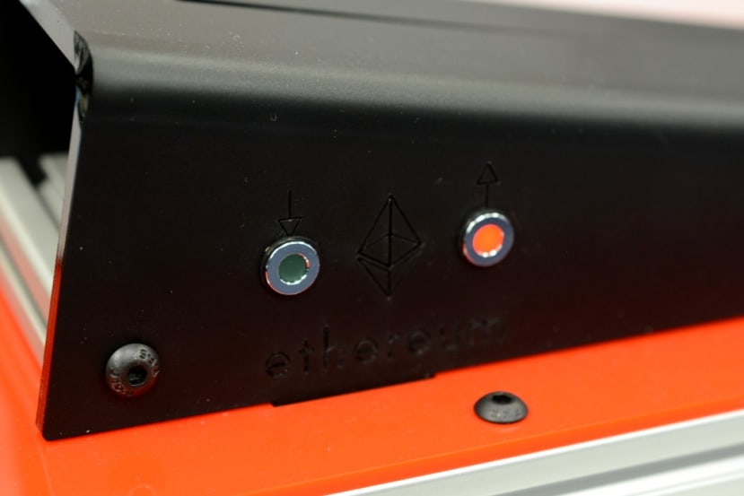
All the demonstrator units also feature a pair of panel mount LEDs:
-
8mm flush hyper-bright red LED (134-5534)
-
8mm flush hyper-bright green LED (134-5535)
These are used to indicate blockchain activity. Every time a new block is sealed by the miner, or with the other units is imported/synchronised, the green LED will flash. When a use case demo unit, e.g. Crash Crash, submits a transaction to be written to the blockchain, its red LED will flash. When the miner seals transactions from the units into a new block, its red LED will flash.
Hence the LEDs provide a very clear visual indication of blockchain operation.
Car Crash

The Car Crash demo unit has a MikroElektronika Accel click module (882-8900) fitted inside the static car. This features an ADXL345 3-axis accelerometer and is cabled to a Pi 3 click shield (162-3385) , which in turn is fitted to a Raspberry Pi 3 Model B+ (137-3331) secured to the back of the demonstrator unit.
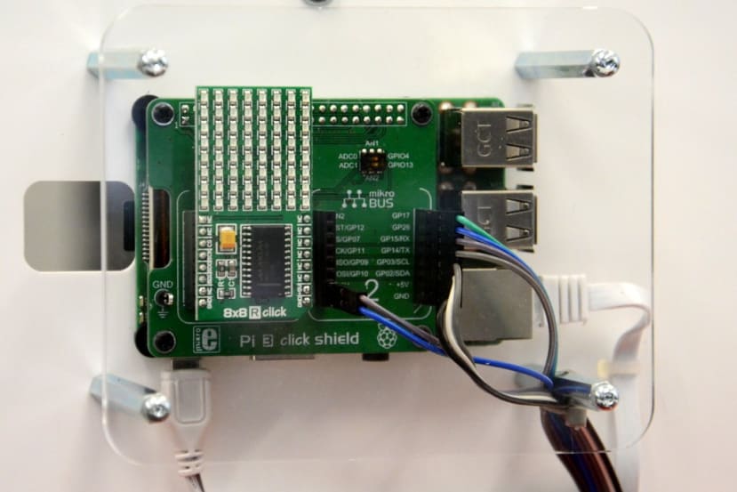
The aforementioned switches and LEDs are also connected via position 2 on the click shield.
Position 1 on the shield is occupied by an 8x8 click red LED module (923-5974) that is used to provide a visual indication when a crash event has been triggered.
Machine Failure
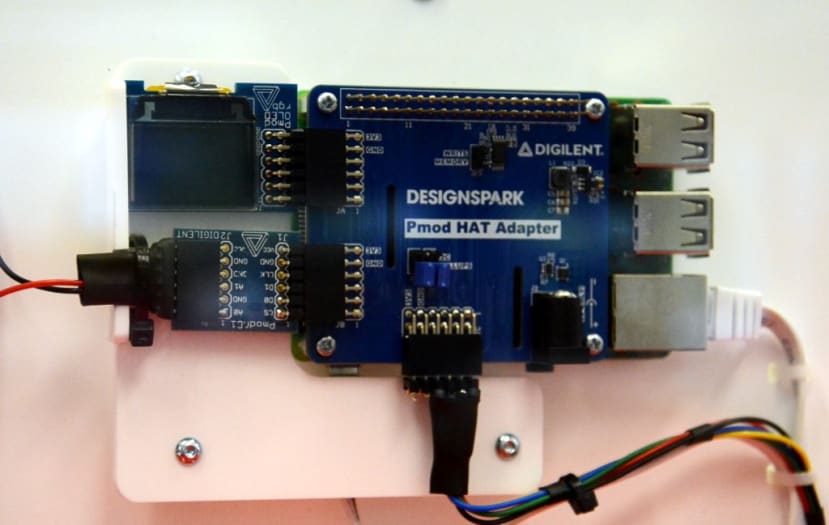
All the other demo units make use of Pmod modules interfaced via the DesignSpark Pmod HAT adapter (144-8419) . Above we can see this fitted to the Pi in the Machine Failure unit, with a Pmod OLEDrgb (134-6481) used to indicate a status of run, stop or failure.
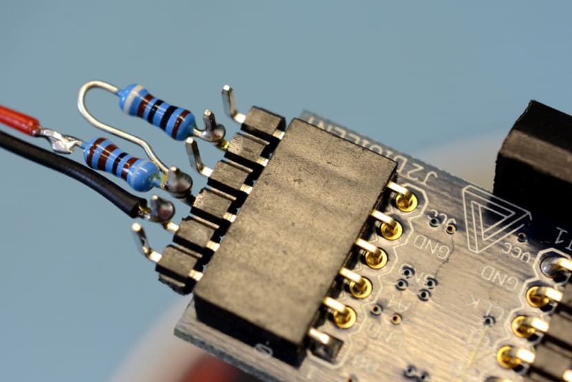
A PmodAD1 12-bit ADC (134-6443) is used together with a simple resistor divider to measure the voltage across the conveyor motor terminals.
A high quality large red momentary push button (137-0013) is used to trigger a failure event.
The third Pmod port is used to connect the buttons and LEDs.
Temperature Alert
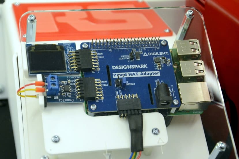
The Temperature Alert unit also makes use of a PmodOLEDrgb, but this time to indicate the temperature as measured by a PmodTC1 plus thermocouple probe (134-6476) .
Again, switches and LEDs are connected with the third Pmod port.
LeakKiller Challenge
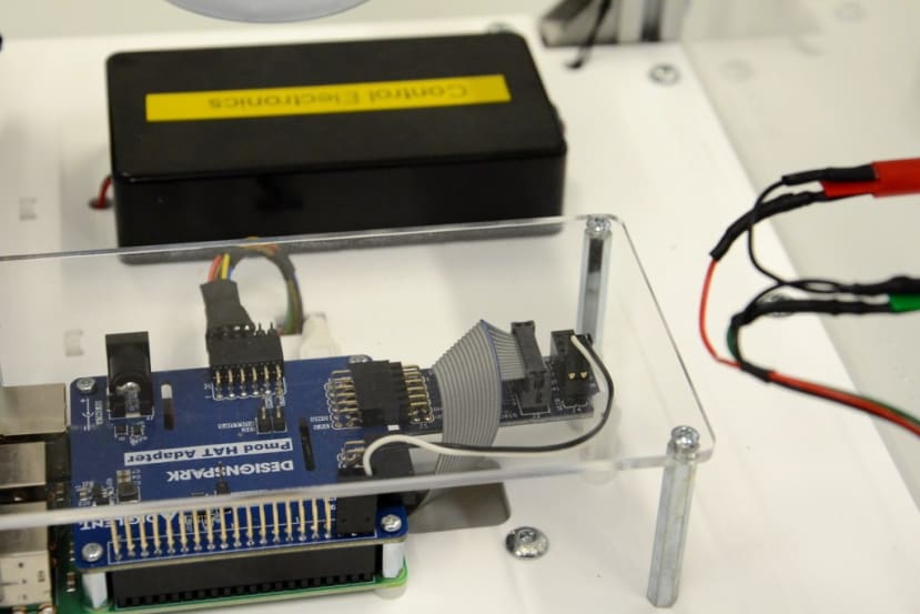
This demo unit has two sides two it: LeakKiller challenge and IoT Blockchain. The former is represented by a large red button that is used to trigger a leak event, which is then simulated by a strip of Adafruit Dotstar addressable LEDs (124-5483) connected via a PmodLVLSHFT logical level shifter (134-6479) , that is configured to interface the Pi 3v3 GPIO output to Dotstar CLK and DATA 5V inputs.
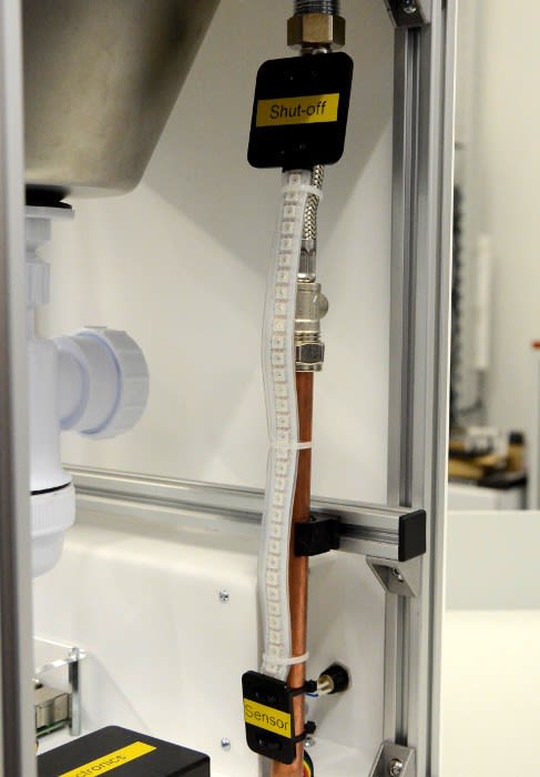
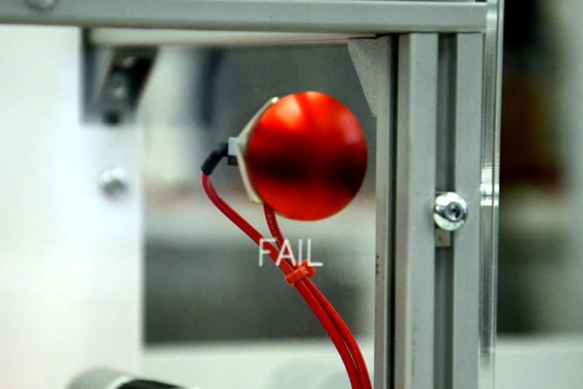
Following a number of drips simulated by a chase of white light, a large red LED in an enclosure labelled Control Electronics flashes, and the simulated leak stops. This simple behaviour demonstrates the basic LeakKiller principle of detecting a leak and shutting off the water supply.
Once the above sequence has completed, a transaction is then logged to the blockchain recording the time of the last leak incident.
Miner
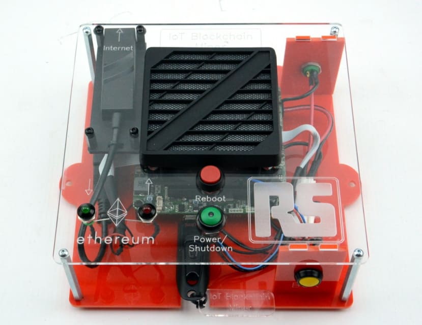
It was decided to use an Intel Thin Canyon NUC Atom E3815 1.46GHz (882-9694) as the computing platform for the miner since if required this could provide quite a bit more processing power than a Raspberry Pi. A flash drive could also be used for storage, meaning that it would be easy to backup and write-out new O/S and application images should the need arise — and with USB 3.0 support it shouldn’t be too slow either.
A particularly nice feature of this Intel NUC model is that it is designed for embedded use and has a Custom Solutions header which provides a selection of handy GPIO. Making it possible to easily integrate the blockchain activity LEDs, along with the BCR button.
Summing up
Quite a lot of thought went into the components selected to ensure that they would be sufficiently aesthetically pleasing and provide a good user experience, with suitably tactile switches and robust power connectors etc.
The DesignSpark Pmod HAT adapter made it easy to integrate incredibly useful Pmods which added small OLED displays, ADC input and temperature measurement to the Raspberry Pi, along with level shifted output for driving the Dotstar addressable LEDs.
In the next post, we’ll take a look at the blockchain network configuration, as much like the mechanical and electronic design, it provides foundations on which to build. Then in the final post, we’ll bring this all together and take a look at the application code.
Other posts in this series
The design and build of the demonstrators is covered over the course of a total of five posts:
- Part 1: Introduction
- Part 2: Mechanical Build
- Part 3: Electronics
- Part 4: Blockchain Network
- Part 5: Host Software