Intruder and fire alarm centre
Follow article Dave from DesignSpark
How do you feel about this article? Help us to provide better content for you.
Dave from DesignSpark
Thank you! Your feedback has been received.
Dave from DesignSpark
There was a problem submitting your feedback, please try again later.
Dave from DesignSpark
What do you think of this article?
This project has been developed as part of a final degree project of the MsC in Industrial Engineering (speciality in electronics) at the Electrical, Electronics and Communications Department of the Public University of Navarra. The aim of this project is to build an alarm centre of a house, which will detect smoke from a fire, the entrance of an intruder or a gas leak. For the intruder detection, it will be necessary to use PIR (Passive Infrared) and vibration sensors. On the other hand, the MQ series sensors will be used for the smoke (CO) and gas (propane) leak detection. To turn off the alarm it will be necessary to introduce the correct password in the numeric keypad.
The development of the project will be divided into three different parts: the electronic circuit design (using DesignSpark PCB), the programming of the microcontroller and the 3D modelling (using DesignSpark Mechanical).
1. Electronic circuit design
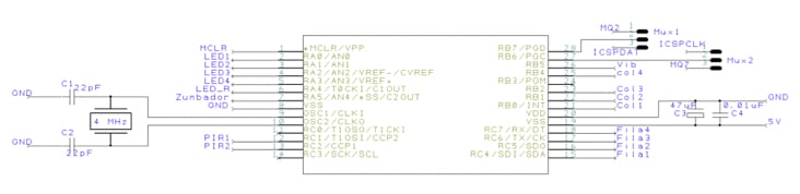
Microcontroller
The control circuit is based on the PIC16F876A microcontroller, which works at 5V. Furthermore, an external oscillator working at 20 MHz (0.2µs per instruction cycle) will be used. In-circuit Serial Programming (ICSP) connector will be used in order to connect the PC with the microcontroller and enable direct programming/debugging of the robot.
Linear voltage regulator
To power up the PCB an 8.4V rechargeable battery will be employed. Since the operating voltage of the microcontroller is of 5V, a linear voltage regulator (7805) will be necessary to decrease the voltage from 8.4V to 5V.
PIR, MQ and vibration sensors
The PIR sensor is composed of three pins: 5V, GND and the digital output, which will be connected directly to the microcontroller. Its operation is quite simple: when the sensor detects somebody, the output pin will change to 5V. The sensibility of the sensor and the frequency of the measurements can be adjusted via two potentiometers.

Both vibration and MQ sensors have four pins including the analog output. Even so, this analog outputs won’t be used, given that, like with the PIR sensors, the pin that will be used is the digital output.
Numeric keypad
A 4x4 numeric keypad (16 pushbuttons) will be used to introduce the password. Each pushbutton will have one end connected to one row and the other to one column.

For the microcontroller to determine which button is pressed, it first needs to pull each of the four columns (pins 1-4) low one at a time, and then poll the states of the four rows (pins 5-8). Depending on the states of the columns, the microcontroller can tell which button is pressed. For example, say the program pulls the first row low and the rest of the rows high. It then reads the input states of each column and reads pin 1 low. This means that a contact has been made between column 4 and row 1, so button ‘A’ has been pressed. To make this possible it will be necessary to use pull-up resistors in the pins of the columns in the microcontroller.
Each time a pushbutton is pressed a green LED will turn on. A 330 Ω resistor is placed between the output of the microcontroller and the LED, when the output is pulled high a 15 mA current will flow through the LED.
Components
The components needed for the development of the project are detailed below:
- PIC16F876A.
- 20MHz crystal oscillator.
- 5V linear voltage regulator.
- 2 PIR sensors.
- MQ2 and MQ7 sensors.
- Vibration sensor.
- 4x4 numeric keypad.
- Piezoelectric buzzer.
- 4 green and one red LEDs.
- Several discrete components, such as connectors, NPN transistors, resistors and capacitors (detailed in the BOM list attached at the end of the article).
2. PCB design
The design of the PCB has been done with the software DesignSpark PCB 8.0. The components have been placed in order to save as much space as possible. To reduce the number of tracks and vias to the maximum the bottom layer is used as GND plane. The following figures show the 3D representation of the PCB prototype:

3. Programming environment
This section describes the functions of the alarm centre and the number of pins of the microcontroller that are used:
|
FUNCTION |
PINS |
|
PIR sensor (x2) |
2 |
|
MQ2 and MQ7 |
2 |
|
Vibration sensor |
1 |
|
Numeric keypad |
8 |
|
LEDs |
5 |
|
Buzzer |
1 |
|
Total |
19 |
Adding the 5V and GND pins, the external oscillator pins and the modular connection pins, it makes a total of 29 pins out of the 28 pins available in the microcontroller used for this project (PIC16F876A). Given that the pins needed are more than the pins available in the microcontroller, it will be necessary to use multiplexers.
The microcontroller has been programmed using the Integrated Development Environment (IDE) MPLAB 8.92 and the ICD2 debugger as a depuration tool. The programming language used for this project is C by means of the HI-tech compilation tool. All the code has been attached at the end of the article but some of the main microcontroller integrated hardware used in the project is described below.
Timer
The TMR1 has been used for 30 seconds countdown from the detection of the intruder to the alarm activation.
Generation of the sounds
Given that the CCP modules are occupied by the PIR sensors, it hasn’t been possible to implement the generation of the sounds in one of them. Therefore, the signal of the sounds has been generated using delays:
for(k=0;k<2;k++){
for(j=0;j<50;j++){
RA5=~RA5;
__delay_us(956);
}
}
The example above describes the generation of the C note.
Interruptions
The interruptions of the Timer 1 and the change on RB4:RB7 are used for the correct operation of the alarm centre. Given that the MQ sensors are connected to RB6 and RB7, when a gas leak is detected the alarm will sound immediately.
4. 3D modelling
A reduced model of a house (2 rooms) has been made for the implementation of the project. Each room will have a PIR sensor and an MQ sensor. The keypad will be pasted in the front of the house, with 5 holes for the LEDs above it. The front wall of the house has been separated from the rest to make the mounting easier.
