Your Fan Temperature Control Sorted
Follow article
 Dave from DesignSpark
How do you feel about this article? Help us to provide better content for you.
Dave from DesignSpark
Thank you! Your feedback has been received.
Dave from DesignSpark
There was a problem submitting your feedback, please try again later.
Dave from DesignSpark
What do you think of this article?
You know how it is in an open plan office, even with air conditioning it is never quite right for everyone. If you are lucky you'll have a steadily controlled temperature that is considered okay on average. But as we all know, the average is rarely correct for all, be it size, shape, temperature or humidity. Adding to this, on extremely hot days the temperature is pulled up by the outside temperature as it exceeds the average maximum for which the air conditioning system was designed.

Having seen the TMS fan controller and wanting to understand its functionality, it seemed like an excellent opportunity to explore this and see if we could come up with a simple local solution to improve the working environment and other temperature control applications.
In our office within our block of 3 desks, we all have very different individual requirements:
Simon (Mr Super Cool) although liking to be baked on his vacations, prefers for his fingers to be kept cool in the office by a nice steady flow of air (especially when the temperature rises during his frantic typing activities!)
Donna prefers a nice steady temperature with the fan providing some cooling airflow when it gets warm.
Finally, I prefer a more even temperature. I'm slightly tolerant of higher temperatures in summer (allowing me to equate to the nice feeling of summer sun!) but not wanting to be cooked on the very hot days.
We all have different personal preferences for the environment in which we work, and with this project, we should gain the flexibility to control personal fans to improve our working environment.
We picked the TMS development kit (769-2732) for this project as it contained most of the connection leads, plus the TMS controller and simplified the build process. The individual components are available separately and detailed at the end of this article. It appears to offer a very flexible control solution for up to 4 different fans.
Now for the techy stuff...
Connecting up
The fans being used are connected to the TMS controller using fan cables provided in the kit. The fans had flying leads which were easily connected to the fan cables - we used the RS Pro crimp butt terminals (053-4288) .
Fan lead colour coding
Blue –, Red +, White Tacho, Yellow or Violet PWM
(Note: Fans were violet and controller was white lead on the ones we used.)
The fan plugs were then connected to the FAN 1 to 3 connectors on the controller as we were using 3 different fans for our project, allowing 3 different cooling options.
The 2 thermistor cables in the kit were connected to the NTC 1 and NTC 2 connections on the controller.
Our PC was connected using the supplied USB cable assembly between the COM connector on the top of the TMS controller and our PC’s USB.

TMS Graphical User Interface
The GUI was the natural choice as this allowed us to easily see and modify the profiles for our fans in this cooling application. A terminal emulator program can also be loaded if this option is preferred.
The first thing to do is to install the GUI onto your PC. The file is on the link below and you need to download the ZIP file from http://www.ebmpapst.co.uk/en/TMSGUI.html
Instructions are in the file, we could not get the auto install to work on Windows 10 so we added the individual components together with the USB driver and launched the TMS-GUI using the desktop icon.
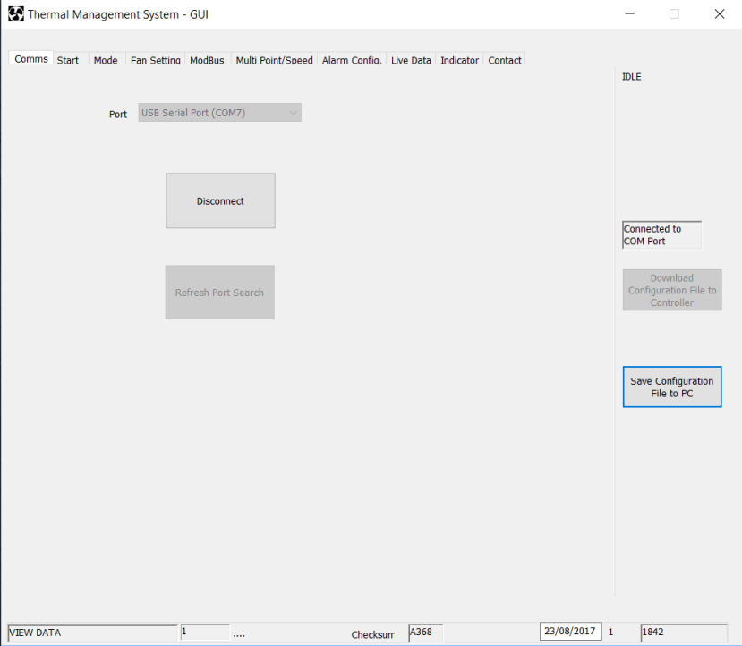
Note: when the GUI has restarted, it is first necessary on the comms screen to select the com port number originally set up (if not in the list refresh the port settings with the controller connected and powered up, and then connect from this screen).
The power lead was connected to the PWR connector on the controller and our bench power supply with Red + and Blue -. The power supply voltage was set to 24V with that being the voltage of the fans we were using. The TMS controller power supply can be from 11V dc to 57V dc max. thus supporting 12V, 24V and 48V fans. We set the supply to 24V, the same voltage as the fans being used.
The power supply to the TNS controller is switched on before running the GUI. All of the LEDs light up initially and then it reverts to the green PWR LED flashing slowly showing power is connected.
Using the GUI the following tabs are present:
Comms tab
Start tab
We skipped to the Mode tab.
Mode tab
We selected temperature sets PWM output (open loop).
Fan Setting tab

This is where the fan specific parameters are set up for each fan being used on the respective FAN connections 1 to 4.
Having 3 fans we entered the respective data for fan 1 to 3.
We entered the Pulses per rev for the fan tacho outputs
Control type was default Open Collector
Ramp rate we kept at 10 the default, this sets the rate at which the fan speed changes 1 being slow to 100 being fastest. In our application, the slower change was preferred for office desk cooling.
The maximum fan speed from the data sheet was used for the individual fans being 9700 for fans 1 and 2 with 3000 for fan 3.
Click “Download Configuration file to Controller” this writes this data to the controller.
The other settings were not required in our design but are available should they be needed.
Mod Bus
This is where mod bus can be setup we skipped this for our desktop application but could be useful for other larger projects.
Multi Point/Speed

This is where you set up the required fan speed temperature profile for each of the connected fans.
Simple 2 point operation is selectable or multi-point with 7-speed set points. We used the 7-speed set points as this allowed for slow changes at the start of the temperature increasing minimising fan speed and noise.
The required thermistor sensor is also selected for each fan. Sensor 1 or 2 allowing different areas to be monitored or 1 and 2 where the highest temperature sensed by either is used for control.
As can be seen in the image seven control points are set with the required temperature and % of speed controlled by PWM. This is done for each fan so 3 in our project. When all of the points are defined the “clean-up/store profiles” must be used to save the changes. The graph will then show the new profiles and these can then be downloaded to the controller by clicking “Download Configuration file to Controller”. After waiting for the transfer to complete the fans start to follow the defined profile.
This process was repeated until the desired control temperature fan speed was achieved for all of the 3 fans we were using. The configuration file then saved to the PC by clicking “saving the configuration file”. With the controller configured it will run to this profile until it is updated again. The PC USB connection can be disconnected and the controller run remotely working to the same profile even after switching off.
In our project, this allowed the 3 fans to be set up exactly to meet the requirements of Donna, Simon and Jeff and controlled the fan speed to meet their needs. We are using both temperature sensors but since it is a small area we could manage with just one. But it could be used in a much larger area where the 2 sensors would be ideal and the fans closest to these could be allocated them.
Click “Download Configuration file to Controller” this writes this data to the controller.
Alarm Config
This screen allows a comprehensive range of alarm conditions to be set covering fan failure NTC sensor failure plus upper and lower temperature limits etc. In our office ventilation project we did not set this up as we were constantly there but a very good set of alarms for failure monitoring where failures are more critical.
Live Data
Here Live data covering the fan operating parameters and measurements are available when connected to the TMS controller. The “View Live Data / Start Logging button will enable this function.
Indicator
This is the GUI indicator screen it displays fan RPM and set speed for each fan connected so we see data on fan 1, 2, 3 with no data on 4 as we are just using 3 fans. The current temperature for sensors NTC1 and NTC2 and also alarm output status. In the project, we used this screen to understand the exact operation of the fans as we adjust our multi point speed profiles for different set temperatures. We monitored on this tab and changed the profile values in the multipoint / speed tab in order to reach the required operation for cooling and minimum noise.
A slight delay is present as the data from the controller is read, then the indicator screen updates to the current point.
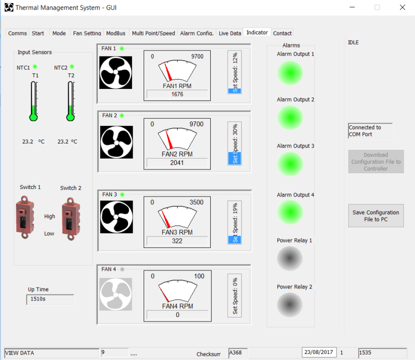
Image indicator panel

Image indicator panel higher temperature NTC1
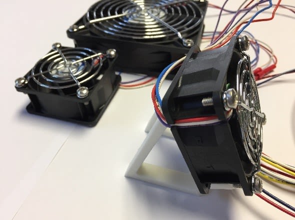
When the project was up and running we positioned fans on our 3 desks with the 2 temperature sensors spaced apart giving coverage for the two ends.
We used some small 3D printed stands to angle the fans plus fitted fan guards for added safety
The controller had profiles set up for each individual fan and the individual's requirements. We adjusted the multi point profiles in order to get the optimum operation. When set up and running as required the controller was just used on its own and provide an excellent level of control providing additional fan air circulation matching the needs of everyone.
We picked 2 different types of fans. The larger 119 x 119 new high-performance fan offers reduced operating noise thanks to a new aero-acoustic design. This was certainly the case and it provided very low noise when operated at the lower speeds with a nice wider air flow ideal for background desk cooling. The other fans were more compact 60 x 60 fans which would operate up to a much higher speed of over 9000 rpm. They were naturally more noisy at the high end but worked well at lower speed giving directional cooling for Simon's fingers on the keyboard.
This is one of those projects which when you get it up and running and see it working you understand how powerful and flexible it is covering a whole spectrum of applications. Designed for use with DC compact and centrifugal fans having four wires (PWM speed setting and tachometer output variants) with a maximum current of 11A makes it extremely versatile. Can also be used with 230V EC fans if a TMS power supply is added. Applications cover single fan control up to 4 separate fans which each can have their own multi point speed control profiles with a choice of temperature sensor options. This functionality together with the array of alarm options should allow numerous applications from our simple HVAC project through to complex industrial process control.
Definitely worth a closer look.
Products Used
TMS development kit (769-2732)
Which consists of TMS fan controller together with all of the cables needed, plus 2 thermistor leads used for temperature monitoring.
The components can be purchased separately, if required, as below:
- TMS fan controller (769-2722)
- Configuration lead (769-2726)
- Two thermistor cables with integral thermistors (769-2735)
- Cable kit (769-2738)
Power cable, 4 fan cables, alarm cable and switch input cables with the correct mating connectors for the TMS controller. The other ends are free for connection as required.
In addition, we used:
- 2 x 624/2H3P ebm-papst DC axial fans 24V (800-4303)
- 1 x 4314N/2HP ebm-papst DC axial fan 24V (136-0667)
- Fan guards offering finger protection
- Fan finger guard 119 x 119 (101-8096)
- Fan finger guards 60 x 60 (025-0892)
- 3D printed stands for the fans
If required, separate fan connectors are (679-5776) and (215-5887) for female crimp contacts.