Comparing DesignSpark PCB and DesignSpark PCB with Engineer Interfaces
Follow article
 Dave from DesignSpark
How do you feel about this article? Help us to provide better content for you.
Dave from DesignSpark
Thank you! Your feedback has been received.
Dave from DesignSpark
There was a problem submitting your feedback, please try again later.
Dave from DesignSpark
What do you think of this article?
You might be wondering what the buzz around DesignSpark PCB with Engineer plan is. If you have been using DesignSpark PCB for a while and not sure whether it is worth switching to the professional version, keep reading this article to learn about how each software is different in terms of the user interface.
Creating A Technology File
So, we are starting with creating a new technology file. If you do not know what technology file is, think of it as an equivalent of Microsoft Word. Every time you write a new article or report in the word processor, you style your text and fonts differently. Similarly, creating a technology file allows you to utilize the same design settings, such as units, grid size, track width, etc., for different projects. This is useful, for example, when you are using the same company for manufacturing and they have their own specifications.
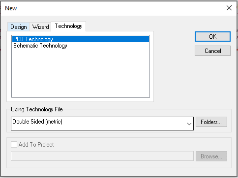
To create a new technology file in DS PCB, go to File - New - New Technology File. A new window will pop up, where you can choose if you want to create a Schematic or PCB Technology File. From Copy From File option, you can select the technology file that you can use to start with.
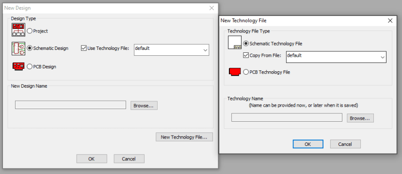
Creating a technology file in DS PCB
Creating a technology file in DS PCB with Engineer plan
In DS PCB with Engineer plan, you will notice that the dialogue window is a bit different. You will see a separate tab called Technology, which has the same options as in DS PCB.
Units
Once a new window for Technology file window comes up, you can start by specifying the measurement unit for your design. In Settings, you have the option of specifying Imperial or Metric units. In DS PCB with Engineer plan, however, you can toggle between units using shorthand <Shift-I>, which is very useful when you need to work with both Imperial and Metric units.
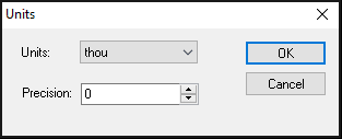
Choosing units in DS PCB
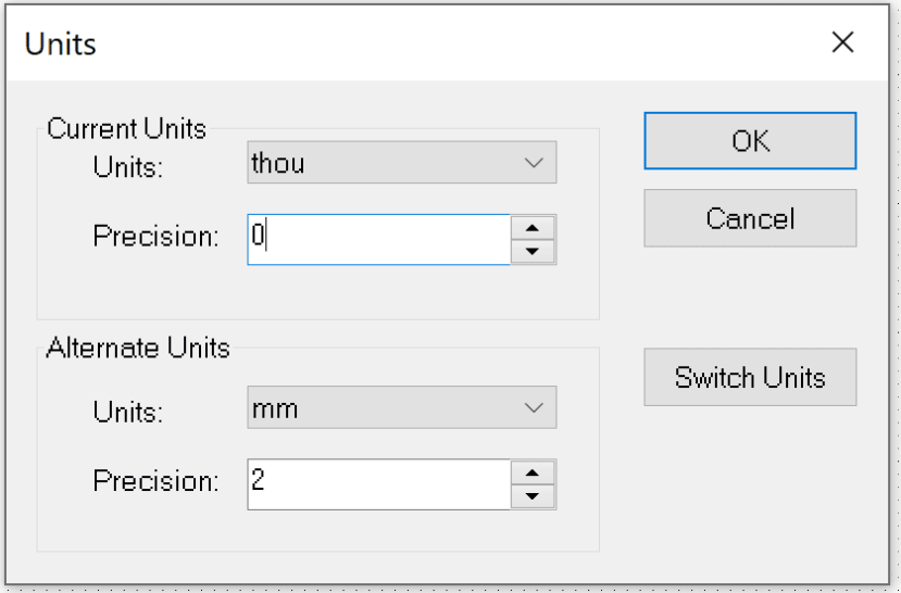
Choosing units in DS PCB with Engineer plan
Grids
Grids dialogue comes with more options in DS PCB with Engineer plan. You can create and save you own grids with its own display settings. You can also use polar (radial) grids. The Grids dialogue is available through the Settings menu for both software.
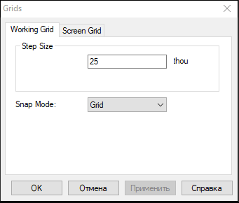
Grids in DS PCB
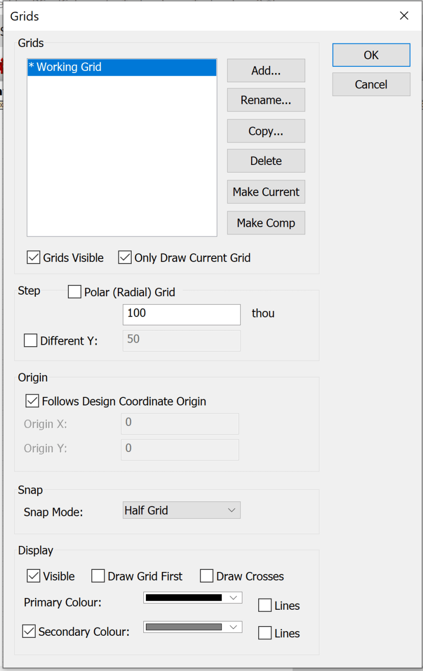
Grids in DS PCB with Engineer plan
Design Technology
This dialogue is used to define styles for the design. This might include shape and size of pads, text and line styles, connections, etc. Along with previously available settings, you can now define the Hatch style, assign a system Value Name to your components and create Variants of the same design in DS PCB with Engineer plan. Other options include adding and modifying Blind and Buried vias in Layer Spans dialogue, assigning which rules should be kept and which are not for the components in Component Rules, and specifying the allowed wire length in Wire Length.
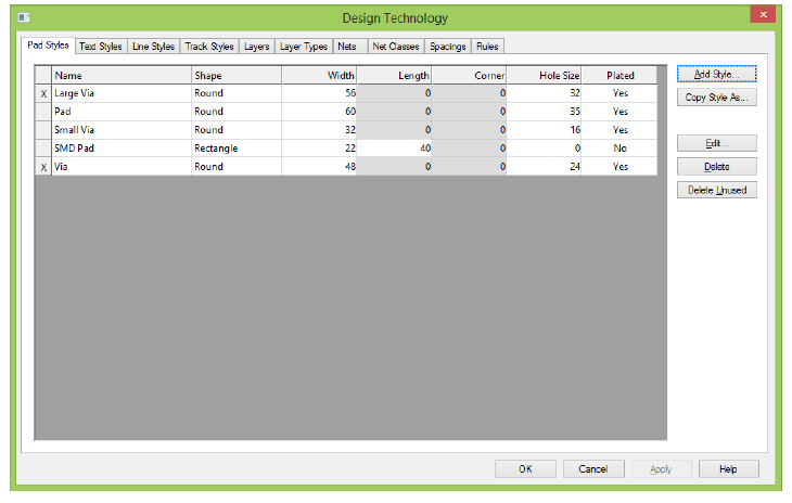
Design technology dialogue window in DS PCB
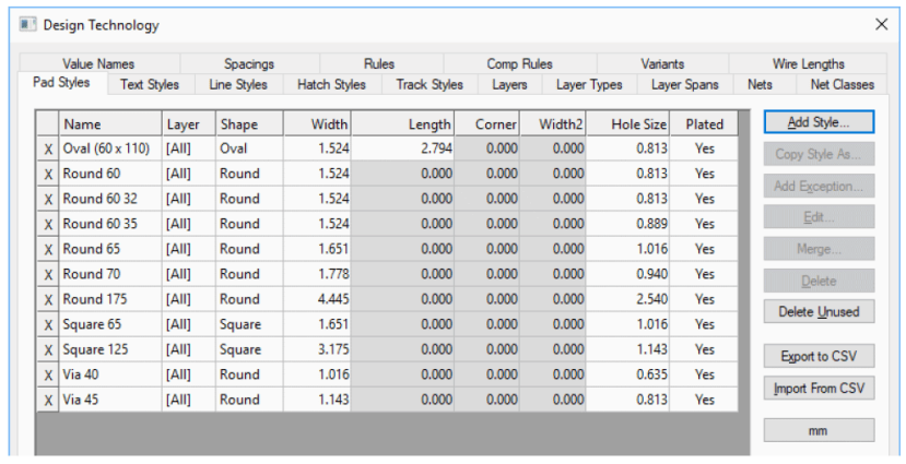
Design Technology dialogue window in DS PCB with Engineer plan
Colours
In Colours dialogue you can change the colour of any design item. DS PCB with Engineer plan comes with a lot more options for this dialogue as compared to DS PCB. For example, you can now use autofill when creating new symbols such as op-amps. You can also specify colours for Nets and Net Classes. The colour setting can be saved in Colour files and be used again for other designs.
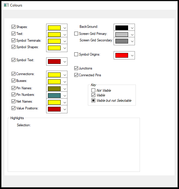
Colours dialogue in DS PCB
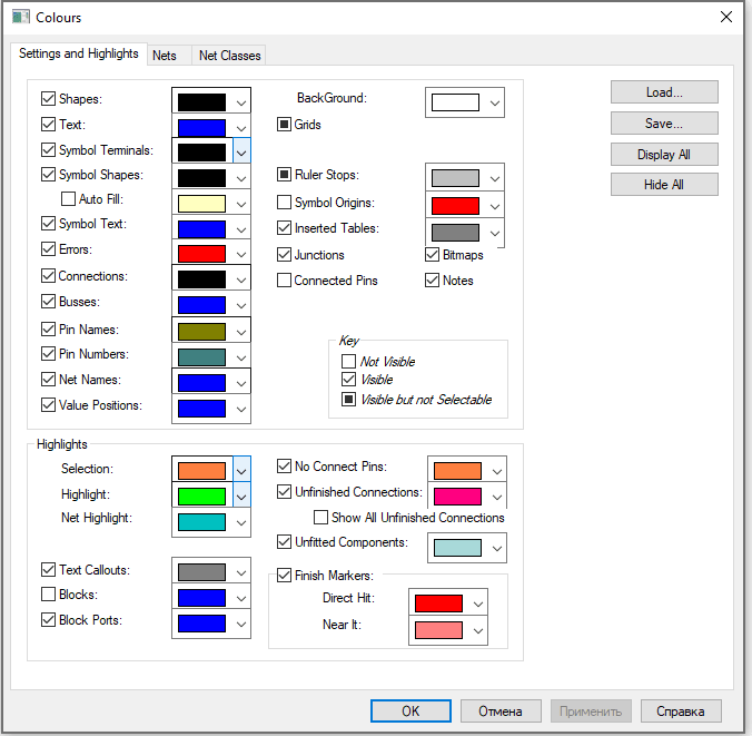
Colours dialogue in DS PCB with Engineer plan
Customise
Apart from defining keyboard shortcuts for commonly used functions, this dialogue in DS PCB with Engineer plan allows to edit the Toolbar, Menu and Commands as well as edit some general features in Options. You can customize the user interface by changing the visibility of the Toolbars from the list of available toolbars. In the Menu tab, you can define what type of menu needs to be displayed for different types of design. Lastly, in the Commands tab, you can drag and drop commands that you wish to keep on the toolbars.
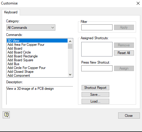
Customise dialogue in DS PCB
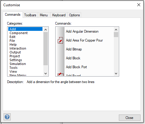
Customise dialogue in DS PCB with Engineer plan
Preferences
In DS PCB, you have the option of working with dual screens. In Settings - Preferences - Dual Screen tab, you can specify how you want to arrange separate instances on multiple monitors or on a single large screen. You can also modify interaction features (e.g. mouse sensitivity) separately for schematics and PCB designs. DS PCB with Engineer plan comes with a separate dialogue for editing the properties of PCB Tracks. The warnings that are displayed in the application window can be enabled or disabled in Warning tab of Preferences section.
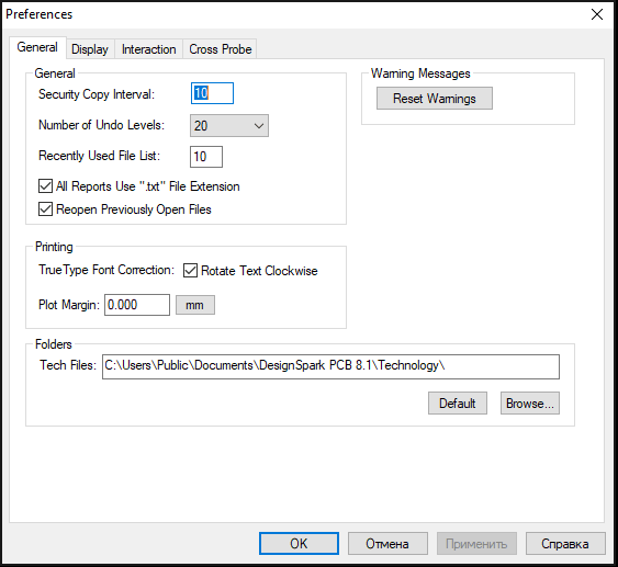
Preferences dialogue in DS PCB
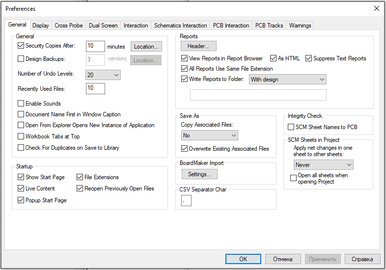
Preferences dialogue in DS PCB with Engineer plan
Schematics & PCB Design
Some of the new features when it comes to the design files are described here. First of all, there are Cutout and Merge options that were not previously available in DS PCB. This is particularly useful when drawing both Schematics and PCB symbols. Secondly, DS PCB with Engineer plan now comes with the multi-level hierarchical design. This allows the creation of more structured designs by breaking down a problem into functional elements and tackling each of them individually or so-called “Top-down” approach. Another method is called “Bottom-up”, where the common circuit elements are re-used by saving them in “blocks”. In Settings - Add menu, if you choose Block option, you will be able to specify a block name and the content design. Additionally, the documentation process can be improved tremendously with new features like Bitmap, Design Notes, and Text Callouts being added to your design. Lastly, Schematic DRC, which allows you to perform a large range of checks, including unconnected pins, can now be performed to minimise design error at schematics stage.
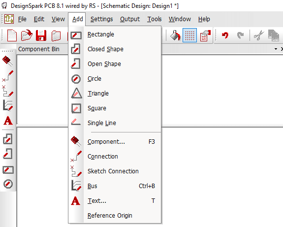
Schematics design dialogue in DS PCB

Schematics design dialogue in DS PCB with Engineer plan
The routing game in DS PCB with Engineer plan has improved dramatically. We have another article on DesignSpark that features some of the routing capabilities. On top of that, you can now use Blind and Buried vias in your design. DS PCB with Engineer plan has a more extensive set of design rules in DRC dialogue, including thermals and components check. Extra items that do not need to be on the board, but you still want to include them in Bill of Materials (BOM), can be kept in the Associated Parts section. Drill Table and Layer Stack graphics can be added to the design from the Documentation. You can start enjoying the benefits of mass production by accommodating multiple PCB designs on a single layout. This is available through Panel Wizard dialogue.
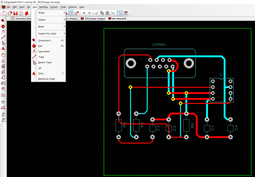
PCB design dialogue in DS PCB

PCB design dialogue in DS PCB with Engineer plan

Drill table and layer Stack information in the PCB design
In case you only have access to PCB design files, you can reverse engineer back to schematics containing components and connections which represent the same netlist as that defined in the PCB in Reverse Engineer dialogue. Different versions of the design file can be analyzed in Design Revision Analyzer to find any significant discrepancies. Another useful feature of DS PCB with Engineer plan is the ability to include Teardrops and Auto Fanout.
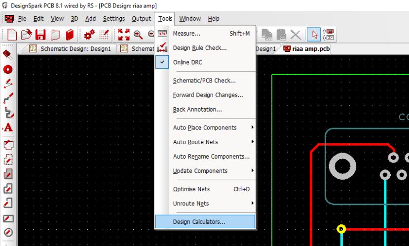
Tools design dialogue in DS PCB

Tools dialogue in DS PCB with Engineer plan
Have you tried DS PCB with Engineer plan already? If so, add a comment below of your favourite and most useful feature.
If not, the free 7 day trial of subscription is a great way to try out DS PCB with Engineer plan.