One Shield to rule them all...
Follow article
 Dave from DesignSpark
How do you feel about this article? Help us to provide better content for you.
Dave from DesignSpark
Thank you! Your feedback has been received.
Dave from DesignSpark
There was a problem submitting your feedback, please try again later.
Dave from DesignSpark
What do you think of this article?
Three Shields for the analogue inputs under different variable resistor dye;
Six Shields for the digital outputs doomed to switch between light ('1') and dark ('0');
Two Shields for the digital inputs where the noise can't lie;
Four Shields for the synchronous and asynchronous serial communication mark;
One Shield to rule them, One Shield to power them, One shield to perform all the Arduino UNO projects at the same time.
The idea behind this project came out from the electronics student association "i2tec" at the Public University of Navarra. The society was preparing a PCB soldering introduction course and needed a PCB with different components and sizes for the training. They were wondering for some days about the kind of PCB that would satisfy the previous requirements and at the same time be useful for the users after completion of the course.
Finally, they came up with a solution: "Why not put all those Arduino shields together in a single PCB". It would help the association when preparing the Arduino courses material, as well as being useful for the users to practice with a versatile and multipurpose shield instead of single-purpose application shields.
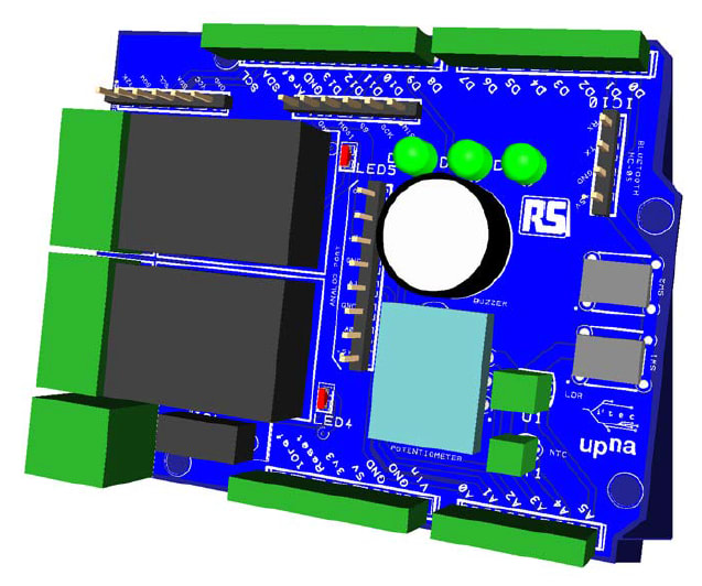
After several discussions and negotiations, a final project idea was selected as the best solution for the projects to be developed by most of the users as well as for future applications. This shield would include:
- Three analogue inputs (potentiometer, NTC and LDR)
- Six digital outputs, three of them connected to green LEDs, one to a piezo buzzer and two digital controls connected to two relays (with LED indicator)
- Two digital inputs connected to mechanical switches (one without debouncing capacitor)
- Multipurpose analogue port for three inputs (with ground and VCC)
- Four communication capabilities, one I2C communication (EEPROM), one socket for real time clock (DS3231), one socket for HC-05 Bluetooth (UART) and one SD module socket
- One multipurpose analogue socket for three inputs with ground and power

The layout was firstly designed by a highly skilled electronics association member (Diego Bailos), who was in charge of the PCB soldering course and after several trials, the components fitted all together in an orderly manner into the shield.
The project was finally decided to be shared for joy and fun of all the DesignSpark community and it can be downloaded and modified freely from the attached file.