Building your own self-balancing robot
Follow article Dave from DesignSpark
How do you feel about this article? Help us to provide better content for you.
Dave from DesignSpark
Thank you! Your feedback has been received.
Dave from DesignSpark
There was a problem submitting your feedback, please try again later.
Dave from DesignSpark
What do you think of this article?
History
Self-balancing robots exist since the mid 80’s, when Professor Kazuo Yamafuji built the first model that could simulate the behaviour of an inverted pendulum. Since then, many different prototypes have been built, but the widespread accessibility of electronic components has made it a very exciting project for makers.
The aim of this article is to present a small self-balancing robot based on Arduino and give some tips for its construction. This robot should be able to maintain balance on two wheels by using a digital PID control. Also, in order to control its movement using a smartphone, a wireless communication module based on Bluetooth will be added.
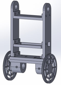
Mechanical design
For the construction of the robot it will be necessary to design and build a structure where you can fit all the different components. In addition, it is highly advisable that this design is modular and easily modifiable in order to be able to make modifications or replace broken parts. For this reason, 3D printing was chosen, being the different pieces that constitute the robot attached in this article.
Electronic components
Arduino nano
To control the robot we have used Arduino because it is a small, complete, and breadboard-friendly board based on the ATmega328. The version used has been the Arduino NANO, as its functionality is similar to the Arduino UNO, but in a smaller package. It also lacks a DC power jack and it works with a Mini-B USB cable instead of a standard one.
Inertial measurement unit MPU-6050
The inertial measurement unit are electronic devices that measure and report about velocity, orientation and gravitational forces to which the device is subjected. IMUs combine information from various sensors, mainly magnetometers, accelerometers and gyroscopes. To use an IMU correctly, it will be necessary to combine the measurements of both devices. For this, two different methods are usually used:
- Complementary filter: based on the combination of a high pass and low pass filter. This filter main advantages are, easy implementation and low computational cost.
- Kalman filter: the algorithm was in 1960 by Rudolf E. Kalman. It allows to combine the information of different noisy sources minimizing the error through a predictive loop. Although better measures are obtained, the computational cost is much higher.
The aim of this process is to obtain a measure as realistic as possible of the navigation angles of the object. These angles are defined by solving the problem of determining the position and orientation of an object relative to a base in a three-dimensional space. Allow the relative orientation of both systems to be expressed by describing the orientation of an object by three orthogonal rotations about the X (roll), Y (pitch) and Z (yaw) axes. In our case, the MPU-6050 IMU was used, which incorporates a gyroscope and an accelerometer and is accessible using the I2C communication bus.

Gravity's acceleration is used as reference to calculate the angle that the accelerometer will use. An accelerometer is not a suitable sensor to determine the speed of a system, much less its position. So another tool must be used to get the value of the inclination value:

A gyroscope is a device that allows us to measure the angle of rotations rotated by a certain mechanism. These devices, unlike the accelerometer, are purely differential devices, so that angles relative to an arbitrary reference are always measured. The main problem of gyroscopes comes from having to obtain the measurements through an integration, an accumulation of errors will occur in the measurement, causing a drift in the measurement, medium and long term, with respect to its real value.
The basic idea behind a complementary filter is to combine the two outputs obtained with the accelerometer and the gyroscope to obtain a good estimate of the orientation angle. The filter will behave as a low-pass filter for the measurement of the accelerometer, and as a high pass filter for the gyroscope measurement. In this way the high frequency components of the accelerometer are dominated by the gyroscope. The mathematical way to implement this filter is:
Where FC is a constant defined by the user which has usually a value between 0.85 and 0.95.
Bluetooth module HC-05
Because we want to be able to control the robot using a smartphone, the easiest solution found was to use a bluetooth wireless communication module. The chosen device is a bluetooth module HC-05, which can be controlled using a communication via serial port.

The serial port for this communication has been created using the library SoftwareSerial. This library allow us to define a software serial communication element on user-defined pins.
DC motors with encoders
In order to grant movement to the robot it will be necessary to use motors. From all of the engines available (brushless, stepper…) we chose DC engines because they have good torque and speed control.

This kind of engines have built-in incremental type encoders, so that the calculated speed measurement can be obtained by the time it takes the rotor to take a turn. The direction of rotation can be understood by comparing the two square signals we receive from each of the encoder phases.
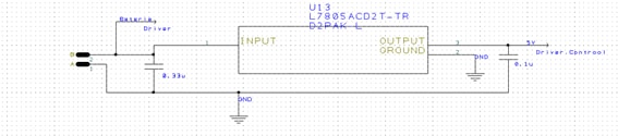
Voltage regulator LM7805.
The voltage regulator LM7805 is a device that allows us to switch from the voltage of the battery to a constant 5 volts across the board. This device is able to withstand a current of 1A, making it ideal for our project. The connection scheme of this device is as follows:
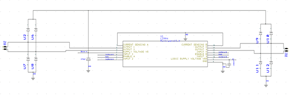
Driver L298N
A motor driver is a device, or group of devices, that is used to control in a predetermined way the operational performance of an electric motor. The driver used for controlling and directing of rotation of the motors is the driver L298N from ST Microelectronics. This allows a current of 3A per channel, so it can withstand the intensity demanded by the motors. The problem with this driver is that it does not have a diode bridge, so it will be necessary to add one to the board. Another element that is added is a large capacity electrolytic capacitor that helps regulate the voltage of the motors. The connection scheme is as follows:
2200mh LiPo battery
Lithium-ion polymer batteries are suitable for this type of application. In order to supply the necessary power demanded by the motors and the necessary power for the correct supply of all the components of the PCB, a LiPo battery of 11V and 2200mah will be used.

PCB design
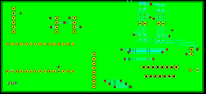
To complete this task, we have used the software DesignSpark PCB, which allow us to design the electronic card in a simple and friendly way. Before commencing with the design of any of the parts, the correct performance of every circuit was verified in a prototype board. After verifying the proper operation of the each part, the PCB was designed using the software DesignSpark PCB 8.0, and the schematics and PCB files are attached at the end of this article. The PCB has surface of 50x110 millimetres and a two layers board, the top one is for the power supply (5V) and the bottom one for ground. Once the correction of all schematics was verified, the design of the PCB was carried out using the Translate To PCB tool. After the distribution of the elements in the PCB and the creation of the different nets that join the devices, the power and mass plans for the circuit are created.

Bottom layer:
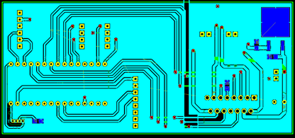
Top layer:
Software
Overview
In order to have a global view of the program, a flow diagram is going to be presented thanks to which it will be possible to follow the program logic. Also, the use of the flowchart will later simplify the programming task by having a clear scheme of it. The flow diagram used to carry this project can be seen in the following figure:
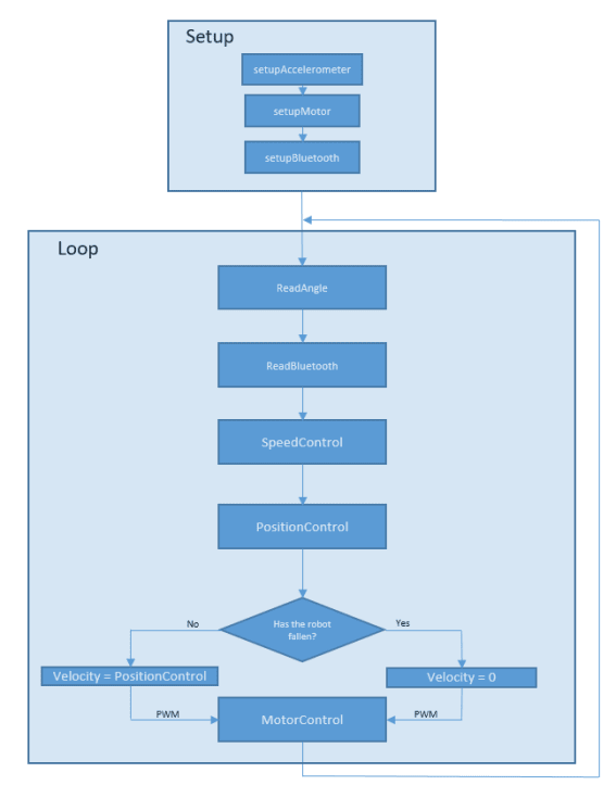
Once the different components have been initialized and the necessary parameters for the operation are set, the program will run as follows:
- Communication with the inertial measurement sensor is started using the I2C bus and the accelerometer and gyroscope data are obtained on all three axes. After receiving this data, the mathematical operations necessary to obtain the inclination angle are performed.
- Bluetooth communication is checked. If data has been received (which will be a character between “a” and “e”, a number or a line break) two different operations will be performed. If the data is a number, the coefficients of the PID controller will change, but if the data is a character, a movement direction is defined.
- Knowing the tuning values of the PID and the direction in which will move, the speed PI is calculated. This will help us to calculate the reference angle that must be followed to maintain a certain speed.
- The control action is calculated by the PID position. The input of this control will be the previously calculated reference minus the angle measured by the inertial measurement sensor.
- Known the control action, which will be a PWM, this will be sent to the driver to control the engines, and ultimately the position of the robot. Another feature to keep in mind is that if the robot falls to the ground, even if the PID generates a control action, this is not taken into account and the speed of the robot in this case is zero, so we will avoid running away when it falls.
Control
It will be necessary to choose a type of controller to make the robot stable. In this case, we have chosen a PID controller. The fundamental idea behind this kind of controller is to read the process variable and get, at the output of the actuator, a compensation value for the input adding the proportional, integral and derivative part. The system to control will be as follows:

PID control Tuning
To establish the values that gain, integral time and derivative time mush have in order for the system to respond correctly, we will use the Ziegler-Nichols method. This method is based on finding the proportional gain value that makes the system to have a sustained oscillating response. At this point, the gain value and the oscillation period are recorded. Once these two values are known, the tuning recommended values are:

PID controller modifications
After programming a first version of the PID digital control, several problems occurred that were solved, thanks to that a much more robust control algorithm was obtained.
Sampling period
All digital controllers depend on the sampling period, and ours was evaluated at irregular periods. A constant sampling period was established so that control works better.
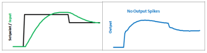
Derivative Kick
This is a problem that occurs due to the derivative section of the PID control. When a reference change occurs, the output of the control becomes very large, so that the actuator can be saturated.
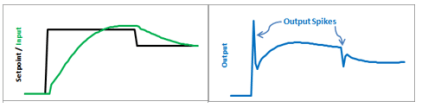
The solution is based on that when the Setpoint value is constant, its derivative is zero, so that the derivative control action becomes:

The peaks in the derivative disappear.
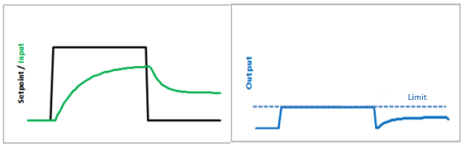
WindUp
This is a problem due to the integral section of the PID control. When an error is maintained over time, this action increases to solve it, but can saturate the actuator.

To solve this problem, what is done is to limit both the control action generated by the PID control, and the action generated by the integral section. This eliminates delays on departure.
Remote control
The Bluetooth Serial Controller application is used for the remote control. This application allows to create a crosshead that help us to control the movement of the robot. It is based on the assignment of an ASCII character to each of the buttons that will be transmitted when pressing each one of them. This character assignment is as follows:

Once it has been agreed which ASCII character corresponds to each of the orientations, this interface is created in the application Bluetooth Serial Controller, so that the remote control of the robot through a Smartphone is as follows:

Problems
While the project was done several minor problems appeared, such as resizing some parts that make the robot, or using a more efficient driver. However, two major issues were found with the DC motors employed, which are:
Dead zone: When using a low PWM value, the DC motor had not enough torque to rotate, preventing us from performing a correct control when small control actions are necessary. For this reason, the tuning of the PID control is so complicated.
Consumption: The other big problem of these engines is the great consumption of each one of them. For this reason, the PCB must be sized in such a way as to be able to withstand currents up to 1.5A and that the battery is capable of supplying it.
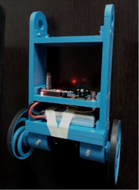
Conclusion?
After following all these steps it is possible to create a project that uses Arduino as the programming basis. Arduino is used because it has a huge community on the internet thanks to which it can solve the possible problems that may appear, in addition to that its price is affordable. Another important area of this project is the electrical and mechanical design that have had to be designed from scratch. The robot already finished is the one we can see in the following image: