Building a ROCK 5B Media Centre
Follow article
 Dave from DesignSpark
How do you feel about this article? Help us to provide better content for you.
Dave from DesignSpark
Thank you! Your feedback has been received.
Dave from DesignSpark
There was a problem submitting your feedback, please try again later.
Dave from DesignSpark
What do you think of this article?

Building a media centre fit for a living room with the ROCK 5B (249-3159) single-board computer.
Introduction
The ROCK 5B is the latest and greatest in the line-up of single-board computers released by OKdo and Radxa, packing plenty of compute and graphics power into a compact Pico-ITX form factor.
We decided to put the compute and graphics power to the test by building a media centre based around the board that should be capable of playing back pretty much any media format.
Board Overview

The ROCK 5B is a powerful, feature-packed SBC that has an unmatched price-to-performance ratio. At the heart of the board is the Rockchip RK3588 SoC, boasting four high-performance Arm Cortex-A76 cores clocked at 2.2-2.4GHz and four lower-power Arm Cortex-A55 cores running at up to 1.8GHz — these utilise Arm DynamIQ technology that enables a blend of cores to be used as appropriate, offering better power efficiency and finer control over performance. Arm has taken a deeper dive into the DynamIQ technology in a blog post.
Paired with the octa-core processor is an Arm Mali G610MC4 GPU with OpenGL ES 3.2 support and an additional high-performance 2D image acceleration module. This is a powerful GPU that is well-utilised by the ROCK 5B and is more than capable of pushing pixels out at a respectable rate to connected displays.
Integrated on the SoC is a Neural Processing Unit (NPU) intended for accelerating artificial intelligence applications. Compatibility with typical frameworks such as TensorFlow, PyTorch and Caffe is offered, with a processing speed of up to six trillion operations per second.
Board variants with a variety of RAM sizes are available, ranging from 4 to 16GB. The board utilises LPDDR4 at a clock speed of up to 4.2GHz and with a 64-bit interface to the processor.
Four display interfaces are present on-board comprising two HDMI outputs, a USB-C port that supports Alternate Mode and a MIPI DSI connector. Up to 8k60p resolution is supported on the HDMI ports, however this is reduced to 4k60p on one port when both are used.
An additional micro-HDMI connector is present on the board, but this has the interesting purpose of being an input, which is not commonly seen on single-board computers. This input appears as a standard Video4Linux device — akin to a USB webcam.
The USB-C port also can be used as a power input, supporting not only USB PD2.0, but a fixed voltage between 9-20 Vdc using a commonly available barrel jack to USB-C adapter. Additional power supply options include using a PoE hat, or connecting a 5Vdc source directly to the GPIO header.
Plenty of on-board storage options are available, including two M.2 slots, an eMMC module connector and a microSD slot. SATA drives are supported through the use of a passive M.2 converter card plugged into the E-key slot. The M-key slot located on the board supports PCIe 3.0 NVMe solid-state drives which offer high read and write speeds.
To round out IO interfaces a complement of two USB2.0 ports, two USB3.0 ports, one 2.5GbE capable Ethernet port, a headphone connector, GPIO header, and a MIPI CSI camera connector are all present. Also included are connectors for an RTC backup battery and 5V cooling fan.
Component Selection
We began our design process by selecting an appropriate ROCK 5B board; 8GB of RAM was deemed to be suitable for a media centre PC, plus this affords cost savings over the 16GB variety.
To provide an additional audio output an OSA Electronics DACBerry ONE+ hat (214-8059) was selected. This provides two extra analogue channels as well as the option of TOSLINK and digital coaxial audio.
Powering the system is an XP Power 5V, 7A SMPSU (230-7341) that provides an adequate 35W of DC power; the recommended power supply wattage for the ROCK 5B is 30W, plus a small additional load due to the extra DAC. A filtered, fused 10A IEC inlet (878-4267) was selected that should help reduce any switching noise from the power supply being conducted back onto the mains supply.
The SBC can thermal throttle under high loads which impacts performance. To alleviate this a suitable 23x23mm heatsink (674-4743) was purchased along with two 25mm, 5V fans (144-2027) and a pack of self-adhesive thermal pads (122-5188) . Having two fans moving air through the enclosure will also provide some cooling for the power supply.
A small I2C OLED display (225-6202) was selected to be mounted on the front panel to provide “now playing” information and system status display. Along with this an illuminated push-button (209-9105) would serve as a power button. A small IR remote receiver (708-5115) is also included for use with a standard remote control.
The rear panel features a HDMI pass-through connector (909-3717) used to expose the HDMI input, plus a set of phono jacks that expose the outputs from the DACBerry hat.
To neatly enclose all the system components, a 1U rack-mount case (810-4377) from nVent Schroff was picked. This features ventilated side panels and ample interior room, with completely removable top, front and rear covers.
Enclosure Design
We started by downloading all the available CAD models for our chosen components. Conveniently a STEP file of the ROCK 5B is available which greatly simplifies designing panel cutouts.
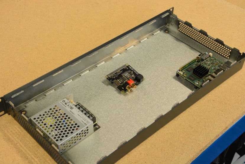
Before laying parts out in a CAD model, we performed a “fit check” by roughly placing the components in sensible locations within the enclosure. This gave a good idea of the space required for cables and reassurance that everything would fit within the relatively small internal Z-height.

To avoid requiring extensions for every port that we wanted to expose, the ROCK board was placed at the back of the enclosure and a series of openings were made. Given the cutouts were to be created by hand, a generous tolerance of 0.75mm was used. This tolerance was not necessary for other openings, although out of preference we tend to oversize drilled holes by 0.1mm, so as to allow for part manufacturing tolerances.
As the power supply has the potential to run warm it was placed close to the right-hand side panel, which is vented. The IEC inlet was also placed to the right-hand side on the rear, which maintains some isolation between the mains and low-voltage DC components.
The front panel consists of a hole to locate the button, window and screw holes for fixing the OLED display, and a small 5mm diameter hole for the IR receiver sensor window to sit in.
No cutouts needed to be created for the fans, as we planned to fasten them using the existing ventilation holes on the left-hand side.
With the CAD model finished and template DXFs created, we moved onto case machining.
Enclosure Machining

MDF templates were laser-cut to use as guides when drilling and filing openings. The templates also serve as a final fit check before committing to starting metalwork.

We then bolted the templates to the panels and provided extra support with masking tape. For larger cutouts, a series of holes are “chain drilled”, which leaves only a small supporting bridge of material. A rotary tool with a burr makes quick work of removing the bridges and then careful hand filing takes the hole to the correct size and shape.
Any small round apertures are drilled to the correct size, with the only step remaining to deburr the edges — this avoids the potential for finger nicks on sharp edges, or the possibility of a metal shaving falling off and shorting against something.
To hide visible, unpainted edges left behind from the machining process, a black permanent marker pen is used. This is not an exact colour match to the grey paint used, but provides enough of a match that is less jarring than bright uncoated aluminium.

When it came to OLED installation time, we discovered that the space provided around the mounting holes on the module do not provide sufficient clearance to add a stand-off without risking cracking the glass display.
To remedy this, a small 3mm thick acrylic spacer was cut. This provides clearance around the mounting holes, but also presses against the edge of the PCB to allow the display mounting screws to be tightened down. Washers were utilised between the nyloc nut and PCB to avoid damaging the fragile FFC.
Given the IR remote receiver is intended to be mounted to a PCB, we had to get creative with our mounting solution — hot melt glue to the rescue. A small dab secured the sensor to the rear of the panel, with the receive window peeking through a hole in the enclosure.
Two fans were affixed to the existing ventilation holes using M3 screws of an appropriate length then wired to the 3.3V supply rail of the ROCK board — thus avoiding the fans running all the time when the mains supply is connected.

Caution: the modification detailed below should NOT be attempted unless you are comfortable with fine-pitch surface-mount soldering. Many small and easily damaged components are present near the power button!
Unfortunately, there are no provisions for an off-board power button. A minor modification involving soldering two small lengths of magnet wire to the power button terminals was performed, after verifying the pinout with the schematic. The terminals were extended to a two-pin header that was glued to the edge of the circuit board alongside the RTC battery header.
An alternative (and potentially preferable) solution would be to add a mains power switch that cuts the incoming 230Vac supply to the SMPSU. This would also cut the “vampire power” draw of having the power supply running continuously, despite the rest of the system not needing power.
Software Setup
Initial setup for the ROCK 5B is easy, consisting of nothing more than writing a ready-to-go Debian 11 image to an SD card. We used Balena Etcher on a Windows machine, which makes the process effortless.
It’s worth noting that the SBC can boot off devices other than the microSD card; Radxa provides a setup guide on their wiki that details the process of writing an image to the NVMe drive, then setting up the on-board NOR flash to hold the bootloader. Instructions are available for Windows, Linux and Mac devices.
With the SBC booted, the first step is to perform sudo apt update && sudo apt upgrade to ensure the system is up-to-date.

A partition needs to be created to set up the NVMe disk for media storage. The command lsblk lists block storage devices and allows us to find the name that our drive was assigned, in this case nvme0n1.
``fdisk`` is a utility that allows for the modification of device partitions and must be run as root. We passed in our block storage device path as an argument, then accepted the defaults when creating the new partition. These changes were written to the device, at which point the tool exited.

A filesystem then needed to be created on the now-partitioned drive, as an empty partition wouldn’t be much use. This was done using the mkfs tool, with a partition type specified as ext4 — this offers no Windows support, but as we do not plan on moving the SSD to another system this is not an issue.

With the drive ready to be used, an appropriate mount point needs to be created. In our case, we created the mount point at /mnt/media. This name can be changed, but needs to be remembered. Permissions were appropriately set to allow the “rock” user access and the fstab file modified to ensure the mount point is available on boot.
Many different choices of media centre software are available; however we settled upon using Kodi, as it is free, open-source, widely used with active forums and a wide range of available plugins, hence making this an easy choice. The installation of Kodi is as simple as running sudo apt install kodi, which also installed all the required dependencies.
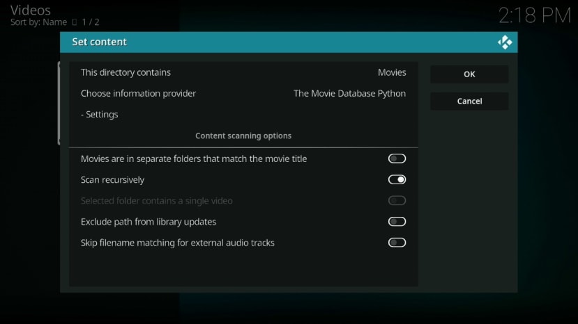
The movies media library was configured within Kodi, since if there are no libraries set up a prompt will appear whenever the application is launched. From there we downloaded two films from the Blender Project that are released under a Creative Commons licence, to use in testing.
Some further configuration was performed to set the default “rock” user to auto-login and then Kodi to automatically launch.
Python Script
A JSON-RPC API is available that can be used to retrieve data and control the Kodi player. This requires enabling the integrated web server, and a few lines of Python could be written that would act as glue between the now playing information and the front panel OLED display.
async def consumer(message):
	global PLAYING
	print("Message data: {}".format(message))
	message_data = json.loads(message)
	if "result" in message_data:
		VIDEO_TITLE = message_data["result"]["VideoPlayer.Title"]
		VIDEO_TIME = message_data["result"]["VideoPlayer.Time"]
		with canvas(device) as draw:
			draw.text((1, 10), VIDEO_TITLE, fill="white")
			draw.text((1, 20), VIDEO_TIME, fill="white")
			if PLAYING:
				draw.polygon(((1, 40), (1, 60), (21, 50)), fill="white")
			else:
				draw.rectangle(((1, 40), (6, 60)), fill="white")
				draw.rectangle(((16, 40), (21, 60)), fill="white")

	if "method" in message_data:
		if message_data["method"] == "Player.OnPause":
			PLAYING = False
			with canvas(device) as draw:
				#if PLAYING:
				#	draw.polygon(((1, 40), (1, 60), (21, 50)), fill="white")
				#else:
				draw.rectangle(((1, 40), (6, 60)), fill="white")
				draw.rectangle(((16, 40), (21, 60)), fill="white")
		elif message_data["method"] == "Player.OnResume":
			PLAYING = True
			with canvas(device) as draw:
				#if PLAYING:
				draw.polygon(((1, 40), (1, 60), (21, 50)), fill="white")
				#else:
				#	draw.rectangle(((1, 40), (6, 60)), fill="white")
				#	draw.rectangle(((16, 40), (21, 60)), fill="white")
		elif message_data["method"] == "Player.OnStop":
			PLAYING = False
			with canvas(device) as draw:
				draw.rectangle(((1, 40), (21, 60)), fill="white")
The Websocket interface code is split into two parts: a producer that routinely polls to get the player status, and a consumer that handles incoming messages to control the display.
Within the consumer code two keys in the JSON dictionary are inspected — “method” and “result”. The “result” key contains the results of a query made to the API, in this case when prompted by the producer function. The “method” key is broadcast when a status change happens within Kodi, such as a user starting or pausing playback and on a number of other events.
When either message is received the display is updated with either a play, pause or stop icon, plus the currently playing media title and duration in minutes and seconds. To control the OLED display, we made use of the excellent Luma.OLED library — this leverages Python Imaging Library to provide drawing functions, which makes it incredibly easy to create graphics and text.
async def producer():
	while True:
		await asyncio.sleep(2)
		return json.dumps({ "jsonrpc": "2.0",
				"method": "XBMC.GetInfoLabels",
				"params": {"labels": ["VideoPlayer.Title", "VideoPlayer.Time"]},
				"id": "1" })
The producer function queries the API every two seconds by sending a JSON string with a number of “InfoLabels” defined within Kodi. These labels expose a great deal of information, with the possibility of selecting multiple labels within one request to reduce the need for multiple calls.
async def consumer_handler(websocket):
	async for message in websocket:
		await consumer(message)

async def producer_handler(websocket):
	while True:
		message = await producer()
		await websocket.send(message)

async def handler():
	async with websockets.connect(KODI_ADDRESS, ping_interval=None) as websocket:
		await asyncio.gather(
			consumer_handler(websocket),
			producer_handler(websocket),
		)

def main():
	asyncio.new_event_loop().run_until_complete(handler())
	while True:
		pass

if __name__ == '__main__':
	main()
As the producer and consumer functions are asynchronous, relying on Python’s “asyncio” library, a handler function needed to be written that would launch both. The function uses the with statement to handle creating and safely disposing of a websocket object, then launches the consumer and producer with asyncio.gather that allows concurrent execution of multiple awaitables.
Writing the display code in Python made for a quick, flexible implementation that could easily be expanded upon in future. For example, more display panels could be added to display system statistics (eg. CPU temperature and load, drive and network utilisation) or more information from Kodi — lots of “InfoLabel” items are available that could be displayed.
Demonstration Video
To Finish
In this article, we’ve taken a look at the ROCK 5B single board computer and the extensive list of features it has to offer. We then looked at the design process to build a media centre based around the SBC, machined and assembled the case, then installed the open-source media centre software Kodi to provide a “ten-foot” user interface.
A small Python script was written that could interface with Kodi and drive an OLED display mounted onto the front panel, demonstrating the usage of the ROCK 5B GPIO interface and flexibility of open-source software.
We have included the DACberry board and IR receiver for future use, with some appropriate software configuration that enables their functionality. A Device Tree Overlay would need to be written that tells the Linux operating system exactly how to configure the devices, and what drivers need to be loaded.