Raspberry Pi 1-Wire Thermostat | Learning Thermostat | DesignSpark
Follow articleHow do you feel about this article? Help us to provide better content for you.
Thank you! Your feedback has been received.
There was a problem submitting your feedback, please try again later.
What do you think of this article?
Reading a DS18B20 temperature sensor with Python on the Pi.
In my last post I wrote about Learning Python and GPIO basics with the Raspberry Pi. This post will develop on my initial experiences by using a DS18B20 1-Wire temperature sensor to build a thermostat.
The GPIO pins on the Raspberry Pi do not have an ADC (analogue to digital converter); the RPi only has digital GPIO, so I decided to use the DS18B20 digital temperature sensor, this works on a digital 1-Wire interface.
Sensor Features
Some of the features of Dallas DS18B20 are listed below:
- 1-Wire interface
- Operating temperatures from -55ºC to 125ºC with an accuracy of +/-0.5ºC when measuring between -10ºC and 85ºC.
- Works on a power supply range of 3.0V to 5.5V.
The full specifications of this temperature sensor can be found in the manufacturers data sheet.
Connecting Hardware
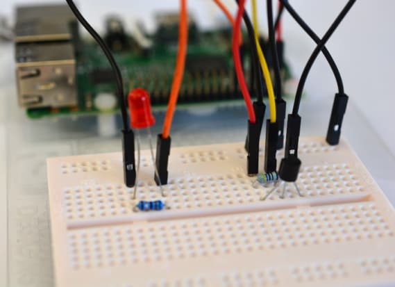
To DS18B20 can be connected to the Raspberry Pi like this:
Pi DS18B20
Pin 6 (GND) - Pin 1 (GND)
Pin 1 (VCC) - Pin 3 (VDD)
Pin 7 (GPIO) - Pin 2 (DQ)
A 4.7K – 10K ohm pull-up resistor should be connected in parallel between VCC and GPIO on the RPi. Since the DS18B20 can be powered between 3.0 and 5.5v I chose to do this at 3.3v on Pin 1 of the Raspberry Pi and using a 4.7K ohm pull-up resistor.
Software configuration
For convenience I prefer to SSH into the Raspberry Pi, so I can connect remotely and not have to attach a monitor, keyboard and mouse.
$ ssh -Y pi@10.0.10.119
I needed to enable using 1-Wire with the GPIO, so to do this I opened an existing text file using the nano command so that it could be edited. I then needed to add an additional line of configuration at the bottom of the file. By enabling 1-Wire this way I didn't need to include any 1-Wire libraries in the code. Now instead the kernel takes care of using the 1-wire protocol to communicate with any 1-wire devices connected to GPIO.
$ sudo nano /boot/config.txt
Then I added a line at the bottom of the file:
dtoverlay=w1-gpio
Next I rebooted the Raspberry Pi to enable the changes. To reboot the Pi you can enter:
$ sudo reboot
Determining the Device ID
Each DS18B20 has a hard-coded unique address associated with it, which means that multiple temperature sensors can be connected on the same bus and all still be accessed individually. By using the line below it will return the unique addresses for your devices (the Kernel creates a directory for each 1-Wire device it detects).
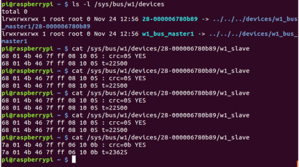
$ ls -l /sys/bus/w1/devices
Accessing Raw Data
To get raw data from the sensor use the cat command to print readings to the terminal.
$ cat /sys/bus/w1/devices/28-000006780b89/w1_slave
Once the raw data has been returned look at the section of the second line which says t=*****, this is the temperature reading. This will need to be divided by 1000 in order to get the value in degrees Celsius.
Using the terminal to get readings from the DS18B20 is great as it quickly proves the temperature sensor is wired up correctly. However, as I want to perform repeated readings and perform an action based on these to build a thermostat, I needed to be able to access them from within code.
Extracting Readings
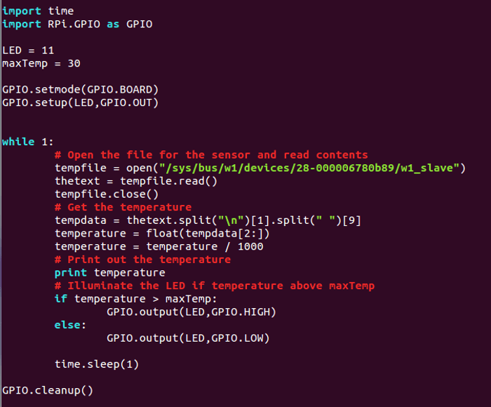
The Python code shown above reads the sensor once a second and outputs the temperature in degrees Celsius. See the comments for further details.
If you prefer you can convert the temperature reading from Celsius to Fahrenheit by including this step and altering the variable name after the print command.
$ TempF = temperature * 1.8 + 32
The code was run with:
$ python Thermostat.py
Triggering an LED
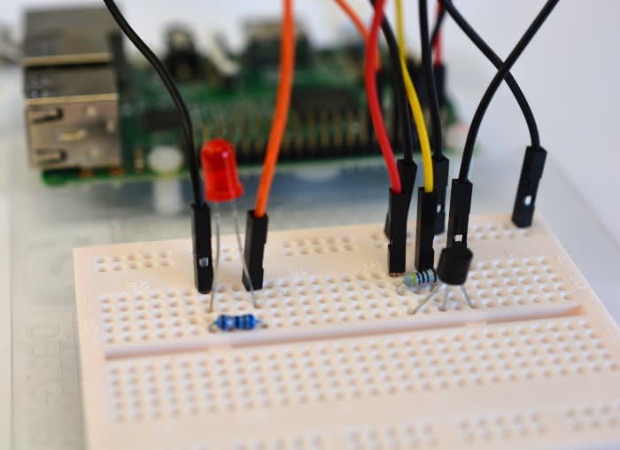
Next I added and LED which would illuminate when the temperature sensor returns a reading greater than a set value, in my case if the temperature exceeds 30ºC.
I simply added an LED on the breadboard and connected the anode via a 68 ohm resistor to pin 11 (GPIO 17) and the cathode to the GND rail of the breadboard.
I updated the Python code by adding the lines which would make the LED illuminate when the temperature sensor had reached 30ºC or above.
Here we have a working thermostat with an LED which illuminates at the point the 'maxTemp' has been reached. Taking readings from a temperature sensor using GPIO on the Raspberry Pi was relativity easy and adding even more sensors could result in some very interesting and cool projects!


Comments