A Practical Introduction to PLCnext Part 2: The Hardware
Follow articleHow do you feel about this article? Help us to provide better content for you.
Thank you! Your feedback has been received.
There was a problem submitting your feedback, please try again later.
What do you think of this article?
In this article, we explore the hardware and software in a little more detail and get hands-on with two simple examples.
The Hardware
In the previous post, we explored the software around the PLCnext Control system, and here we will be demonstrating use of this to program a PLCnext controller.
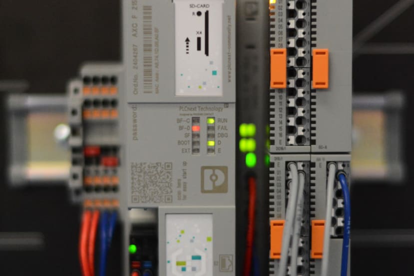
In this example, we are using the PLCnext Starter Kit (205-5854) which comprises of the AXL F 2152 PLCnext controller (177-1391) , the AXL F BP SE4 Axioline Smart Elements backplane, four pushbuttons and a 0-10V slider all installed on a presentation board. The starter kit also includes a 24V plug-top power supply.
When the starter kit is first plugged in, the PLC is completely blank - no program to execute, and the default network settings for connecting to it. This is indicated by the “RUN” light illuminated green, the “D” light illuminated orange and the “BF-D” light blinking red.
A network connection will need to be provided to configure and program the PLC. By default, the IP address for the PLC is 192.168.1.10 - this can be changed from within the PLCnext Engineer software, even if the device is on a different subnet.
As far as the hardware setup goes, this is all that needs to be done! The board is pre-wired to have the pushbuttons connected to the digital input module, the 0-10V slider connected to the analogue 0-10V input module and the digital output module has onboard LEDs for output status indication.
Getting started with PLCnext Engineer
PLCnext Engineer is the IDE (Integrated Development Environment) for configuring, developing and programming PLCnext controllers. It is a free download from the Phoenix Contact website, with additional functionality that requires licensing.
Once downloaded, the installation is straightforward and fairly quick to complete. When opened, PLCnext Engineer displays the Start Page with a number of project options towards the left-hand side.
In this demonstration, we will create a simple ladder logic program that increments a counter when an input is toggled, and turns on an output when the counter reaches a specified value.
To get started, pick the “Empty AXC F 2152 v00 / 2020.6.0 Project” - this will open a new blank project suitable for getting started with the PLCnext Starter Kit. A familiar project view now opens, with “Plant” - equipment, programs and configuration on the left, a central working area, project components such as ladder logic blocks on the right, and a small error list to the bottom. From here, double click on the “Project” drop-down under “Plant”.
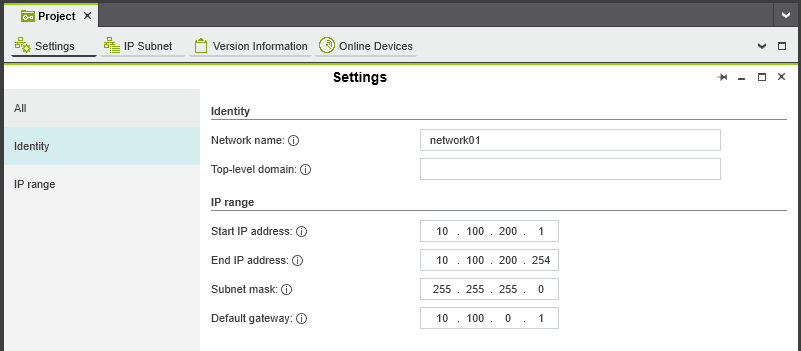
This will open a window that allows you to set network settings for the project, enter versioning information for the project, and discover devices. To start, we set appropriate network settings including start & end IP addresses, the subnet mask and default gateway. Once these details were entered, we headed to the “Online Devices” tab.
A suitable network interface needs to be chosen before PLCnext Engineer can search for online devices. We selected the correct network interface, and then clicked the discover button just to the right of the network interface drop-down box. Once the PLC has been found, the project device settings can be applied to it - this adds the PLC to the project, and then allows for device configuration and programming.
Here we have changed the IP address of the device to one suitable for our network, along with the subnet mask and default gateway. Also from this window, device “flashing” can be toggled which blinks the “RUN” and “FAIL” indicators orange, allowing for easy confirmation that the right device is selected.
Once the device has been assigned to the project, double click the “axcf2152 : AXC F 2152” listing under “Plant” - this will open a window with the PLC “cockpit” which is the main interface for checking the operational status of the PLC, setting the controller into debugging mode, performing restarts and more.
We need to connect to the PLC by clicking the “Connect” button located to the right of the “TCP/IP” dropdown, which will prompt for the username & password - by default this is a username of “admin” and the password printed on the front of the PLC.
Within this window, there is also the option to attach to the PLC runtime, which allows for observation of values in real time, and debugging of programs running on the PLC itself. There are also a number of buttons related to launching the web-based HMI, uploading & downloading programs to & from the PLC, stopping, rebooting and factory resetting the controller.
First, the I/O modules of the controller need to be configured. As we are using Axioline Smart Elements, these need to be configured in the right order - DO16/1 is slot 1, DI16/1 is slot 2 and so on. The slots on the Smart Elements carrier module are numbered, which removes the guesswork from assigning a module to a slot.
Creating a Ladder Logic program
Now the I/O is correctly configured, a program can be created. We begin by expanding the “PLCnext” plant option, then drilling down until “MainInstance : Main” is visible. Right clicking and selecting “Go to type” presents a window where the appropriate programming language can be selected. As we wanted to create a ladder logic program, “NOLD Code” was picked. This then opens a blank ladder logic worksheet where the program logic can be created - this should be familiar to anyone who has used ladder logic before.
We quickly created a counter program that watches for a button input then turns on an output once the counter has hit the desired value.
Variables were then created for the missing contact & coil names, with the appropriate type and usage assigned. The two contacts on the ladder logic program are defined as “IN ports” and the coil is defined as an “OUT port”, which are then connected to the appropriate I/O connections. This is done by browsing to the instance of the program, and connecting the I/O ports.
The completed program can then be compiled and downloaded to the PLC by heading back to the PLC “cockpit” interface, and clicking the “Write project and start execution” button, or by pressing F5 from any window. Once the program has downloaded, the software automatically enters into a debugging mode, where values can be observed and breakpoints can be set to interrupt the program.
It is worth noting that the PLC is automatically put into debugging mode when a new program is downloaded, which stops any program being edited within PLCnext Engineer until debugging mode is exited.
Creating a C# Function Block
In the next example, we developed a simple C# function block that makes an output turn on when a counter value is a multiple of three. Function Blocks are one of the available types of projects to create in C# for the PLCnext controller.
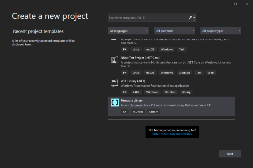
To get started, we installed Visual Studio - the community edition will work, and then installed the PLCnext C# Development Tools according to the guide provided by Phoenix Contact. A new project was then created in Visual Studio, with the PLCnext Firmware Library as the project template.
A suitable name was given, and then the project was created. A new Function Block item was created in the project, by right-clicking on the project name in Solution Explorer, then going to “Add” “New Item”.
This creates a C# code file, with a templated function block created. From here, we wrote code that would perform the counting function. It is worth noting that the PLC environment has a more limited C# implementation, so not every function usually found in a desktop C# development environment is available. This is documented on the PLCnext Info Centre, and also in the “Documentation” folder in the Visual Studio solution explorer.
The project is then built, which produces a file that PLCnext Engineer accepts as a library - this can be added as a user library. To do this, expand the “Libraries” tab under the “Components” pane, then navigate to the output of Visual Studio (this can be found in the Build Output of Visual Studio). Once imported, the library component can then be dropped onto a ladder logic diagram.
More information and documentation for the various programming languages can be found on the PLCnext Info Centre and the forums found at PLCnext Community are also incredibly helpful.
Counter Video
The below video demonstrates the counter working. On every third button press, the D1 output LED illuminates, which is the indicator of the count being a multiple of three.
Conclusion
This was a brief introduction to the PLCnext hardware & software ecosystem, that gives some insight into the wide variety of hardware available, and the versatility of the software environments provided by Phoenix Contact.


Comments