A First Look at the Grove Starter Kit for Arduino
Follow articleHow do you feel about this article? Help us to provide better content for you.
Thank you! Your feedback has been received.
There was a problem submitting your feedback, please try again later.
What do you think of this article?
What the kit contains, trying out some of the modules and building basic projects.
Grove is a modular, simple-to-use system designed by Seeed to easily connect a processor, such as an Arduino, to a wide range of “modules” such as sensors, motors, and inputs. As such, it a great way to quickly prototype projects.
What is in the Green Box?
The Grove Starter Kit for Arduino
(174-3221)
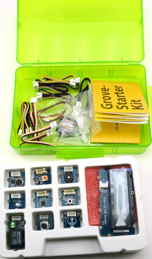
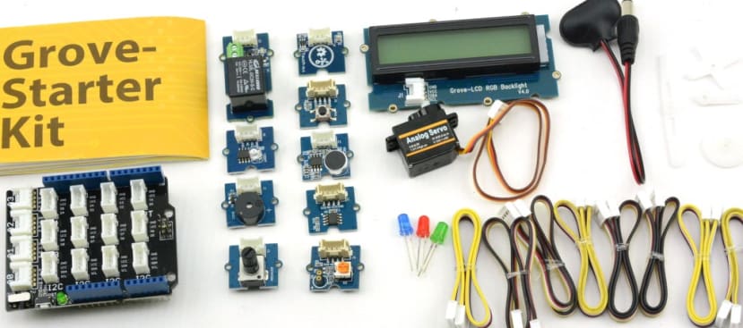
contains the Grove interface – the base shield – and 15 modules that plug into it. The idea is that you can connect any of the modules to your Arduino via the base shield without any soldering or extra wires, making it quick and easy to get started with the modules that are supplied with the kit.
Those are:
- Base Shield 1
- Grove – LCD RGB Backlight
- Grove – Smart Relay 1
- Grove – Buzzer 1
- Grove – Sound Sensor 1
- Grove – Touch Sensor 1
- Grove – Rotary Angle Sensor 1
- Grove – Temperature Sensor 1
- Grove – LED 1
- Grove – Light Sensor 1
- Grove – Button 1
- DIP LED Blue-Blue 1
- DIP LED Green-Green 1
- DIP LED Red-Red 1
- Mini Servo 1
- Grove Cables 10
- 9V to Barrel Jack Adapter 1
All this comes securely packed in a nice green plastic box with a folded A3 sheet of paper, one side of which has information about the included modules and some examples to get you started.
The Base Shield
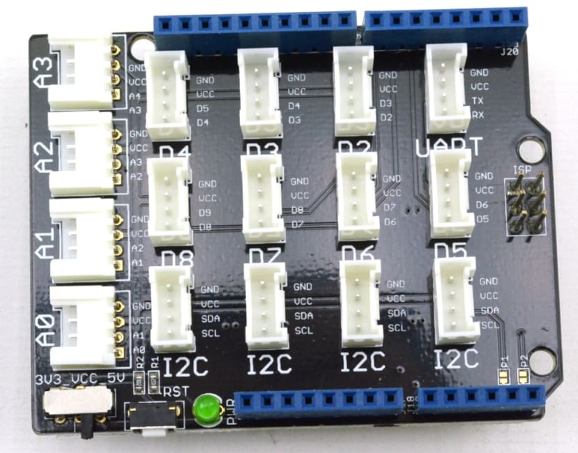
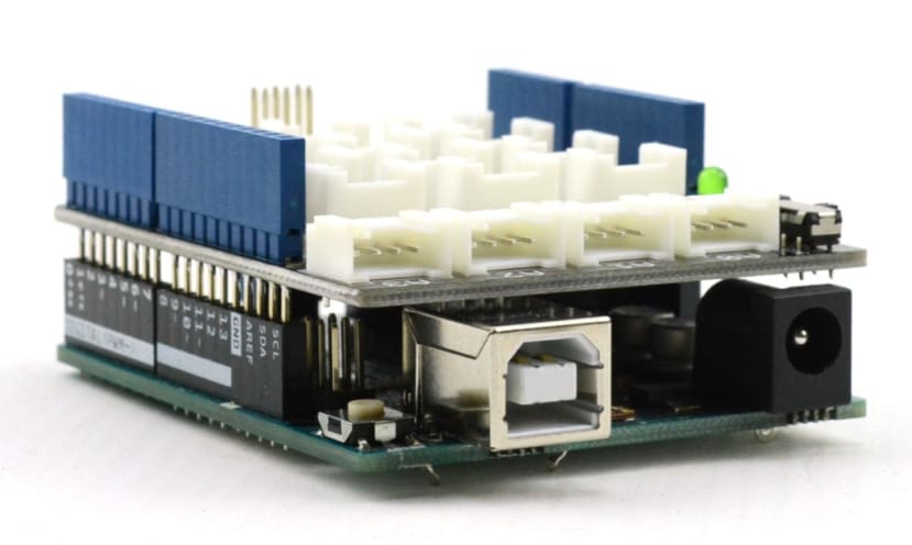
The heart of the Grove system is the Base Shield. It fits an Arduino the same as any other shield and features 8 digital ports, 4 analogue ports and 4 I2C ports. These are all the same 4 pin sockets and so the supplied cables can be used on any of them.
There is also a power LED, a reset button and a power toggle switch to select 5V or 3.3V depending on which microcontroller board you are using. As I am using an Arduino Uno I switched it to 5V.
Modules
Grove produces over 70 different modules. The ones supplied with the kit offer a range of sensors and user interfaces that give a good idea of what is possible with the Grove system. Sensors included temperature, light and sound, other modules include a Backlight RGB LCD, a servo motor, LED, buzzer and all the cables you need.
There is a wealth of support material and as well as the printed instructions that come with the kit, the Seeed web site has a wiki and a Projects section, and their Github is crammed with Arduino sketches and other files to use with the Grove modules.
Trying out Various Modules with the Example Sketches
Sound Sensor
The sound sensor is one of the demos that come with the Starter Kit. I connected the Sound Sensor and LED as instructed (making sure I had the LED the right way round in its socket). The provided sketch set the LED on by default and switched it off when a sound was detected. This seemed the wrong way round to me so I edited the sketch to turn the LED on when a sound was detected by reversing the High and Low setting of the LED pin in the sketch. I also adjusted the thresholdValue to make the microphone slightly less sensitive.
// demo of Starter Kit V2.0 - Grove Sound Sensor
// when sound larger than a certain value, led will on

const int pinSound = A0;               // pin of Sound Sensor
const int pinLed   = 7;                // pin of LED

int thresholdValue = 70;                 // the threshold to turn on or off the LED

void setup()
{
    pinMode(pinLed, OUTPUT);            //set the LED on Digital 12 as an OUTPUT
}

void loop()
{
    int sensorValue = analogRead(pinSound);   //read the sensorValue on Analog 0
    if(sensorValue>thresholdValue)
    digitalWrite(pinLed,LOW);
    delay(200);
    digitalWrite(pinLed,HIGH);
}
Light Sensor
Another simple example that turns on an LED when the light level drops below a set value. Again connecting the modules was simple and the short sketch was easy to edit to alter the level of light that turned the LED on.
I immediately thought how useful something like this could be turning on lights to illuminate the steps up to my front door on dark winter nights.
Slightly More Elaborate Projects
Lucky Dumpling
There is a link to the Instructables page for this project in the kit documentation. It describes it as “a fortune teller box. Press the button to gain glimpses into your future.”
What the instructions failed to mention was that, as this project uses the LCD, I needed to download and install the relevant Library in Arduino IDE.
This was easily done by searching for “Grove” in the Library Manager of Arduino IDE
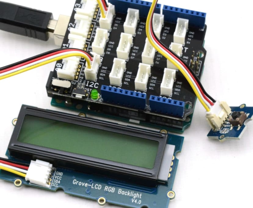
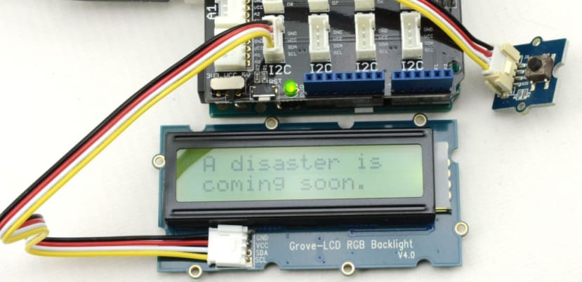
Once the library was installed I connected the LCD to one of the I2C ports and the button to Digital port D4. I then downloaded the sketch from the link on Instructables page and opened it in Arduino IDE. Being full of post-Christmas angst I felt the Lucky Dumpling was far too jolly and optimistic, but that was easily fixed by editing the sketch.
#include <Wire.h>
#include "rgb_lcd.h"

rgb_lcd lcd;

int delaytime = 200;

String msgs1[]= {"A disaster is","You will never","Screaming is the","Live Fast,", "Cry hard and", "Eat well and", "A creative ","They are all", "A dead head","Stay in bed.", "Tempus fugit.", "Bad Luck"};
String msgs2[] = {"coming soon.","be happy.","best medicine.","Die Young.", "feel better.", "get obese.", "mind is a curse.","after you.","is good.","", "", "is coming to u."};

byte bigHeart[8] = {
    0b00000,
    0b01010,
    0b11111,
    0b11111,
    0b11111,
    0b01110,
    0b00100,
    0b00000
};

byte smallHeart[8] = {
    0b00000,
    0b00000,
    0b01010,
    0b01110,
    0b00100,
    0b00000,
    0b00000,
    0b00000
};

void setup()
{
  lcd.begin(16, 2);
  #if 1
  lcd.createChar(0, bigHeart);
  lcd.createChar(1, smallHeart);
  #endif
  randomSeed(analogRead(A0));
}

void loop()
{
  if(digitalRead(4) == 1)
  {
    delay(10);
    if(digitalRead(4) == 1)
    {
      lcd.setRGB(100, 100, 0);
     int randomNum = random(0, 12);
     lcd.clear();
     lcd.setCursor(1, 0);
     lcd.print(msgs1[randomNum]);
     lcd.setCursor(1, 1);
     lcd.print(msgs2[randomNum]);
     delay(3000);
    }
  }
  else
  {
    openning();
  }
}

void openning()
{
  lcd.setRGB(25, 10, 25);
  lcd.setCursor(1, 0);
  lcd.print("Voice of Doom");
  lcd.setCursor(1, 1);
  lcd.print("press to check");
  bouncing(15,1);
}

void bouncing(int x, int y)
{
    lcd.setCursor(x, y);
    lcd.write((unsigned char)0);
    delay(delaytime);
    lcd.setCursor(x, y);
    lcd.write((unsigned char)1);
    delay(delaytime);
}
Uploading the sketch to my Arduino I now had a “Voice of Doom” device that dispensed suitably miserable one-liners.
I am now wondering if it could be adapted to generate Oblique Strategies.
Servometer
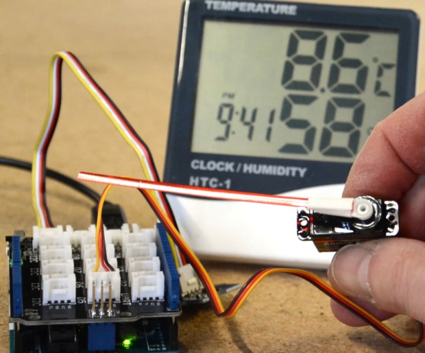
This is a simple temperature detector – a thermometer – that indicates the temperature by moving the arm on the Grove servo motor. Again the instructions, including the downloadable Arduino sketch, are to be found on the Instructables site.
Adding a long arm to the servo makes the reading clearer and it would be easy to calibrate it using an existing thermometer. I just used it to indicate the ambient temperature but I can see how it could be used to monitor refrigeration or the inside of a PC or similar, giving a clear signal when things were going awry.
Conclusion
This kit provides a great introduction to the practical uses of an Arduino combined with various sensors and outputs. It is really easy to get started and Seeed provide some fun introductory projects. The amount of supporting material for the various modules on the internet means it would be easy to develop things further and build some more complicated projects.


