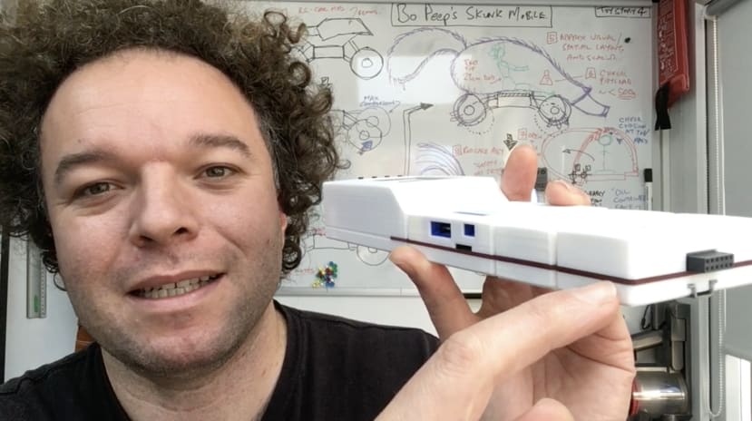
3D Printing Tips with Jude Pullen - Part 2: Pro Engineering and Design Tips
Follow articleHow do you feel about this article? Help us to provide better content for you.
Thank you! Your feedback has been received.
There was a problem submitting your feedback, please try again later.
What do you think of this article?
3D Printing Tips with Jude Pullen: Pro Tips.
Threaded Brass Inserts
Level-up Your Test Rigs and Prototypes.
Using Brass Inserts (M3 Size used here) (LINK) in your 3D Printing can really help if you are making any models which you think you might take apart more than once - either as you are iterating a design, and/or because you might wish to recycle parts also. Another great aspect of using these in the prototyping process, is that if you need something to be reliably interchanged from one configuration to another, you would risk ‘stripping the thread’ with Self Tapping Screws, and so creating a metal-to-metal fixture will allow this to happen significantly more, and with more accuracy.
I originally learned about these at Dyson, when I was a graduate design engineer, where testing and disassembly were common when refining a model. However, since a lot of my work now is open source, I find this is a great way to also allow people to change out components without redesigning everything from scratch.
Oops! - How to Remove Threaded Brass Inserts
For when you make a mistake and need to remove or reset the Insert.
You can use this method for when you mess-up, but also if you simply want to reposition something slightly. It’s a simple trick of heading up the bolt (or some threaded bar - to avoid burns - as shown), and allowing the heat to dissipate into the Insert, and remelt the socket in the plastic.
Aside from this, I also use this technique to reclaim Brass Inserts (as they are about 10p a go, and are totally reusable).
Shadow Gaps
How to make transitions between parts more visually appealing, by accentuating the gap.
Shadow Gaps are one of those things where you will see on many many appliances and white goods, with the possible exception of some smartphones (who have spent millions on Statistic Tolerancing to ensure that the gaps between parts are tiny, but if you are not working at Apple - read on!).
This was a trick I learned from Industrial Designers, who pointed out that accentuating a gap between parts, by deepening the gap and creating shadow, was actually preferable to trying to make things 100% flush, and failing - where the eye will see an irregular line (whereas with a deliberate gap, it will see a transitional area).
Of course, there are exceptions, and it’s fun to ‘break the rules’ when you understand them, and in this instance for the ESDK, I deliberately used a lack of shadow gap to create a visual motif, a red stripe between all the units, which we internally dubbed the ‘Jab Sandwich’. That was only possible because the 3D printed parts could be buffed flat, and the PCBs were by their nature very flat.
Have a go for yourself and see if you find it suits your aesthetic, and function. Secondly, also check out the later videos to see how you can improve print resolution also.
Different Part Tolerances.
How to adjust your design / print settings - for optimal fit.
It might seem obvious, but when printing the majority of a part, chances are the tolerance (accuracy) can be reasonably relaxed - but there might be some areas where it needs to be very accurate indeed. This was the case for the ESDK, where the (white) outer enclosure was printed with a 1.0mm nozzle, in a short space of time, whereas the ‘Sensor Collar’, which had to fit very carefully around the sensor on the PCB, was printed at 0.4mm, and took a comparatively long time to ensure maximum accuracy.
If I printed everything at 0.4 (fine detail), this would be a waste of time, so it was better to print two parts, rather than one. Secondly, because the parts ‘nested’ together, it allowed them to be assembled in a way that further improved the accuracy of the fit of the ‘Collar’ that went around the sensor, as this could be adjusted slightly before glueing in the final position.
Consider how you might divide up parts and/or functions of your 3D print in this way to allow less critical parts to print fast and rough, and critical parts or details to be done in the best resolution.
When To Create Your Own Build Supports.
When you need to go beyond the default print settings and DIY it!
Although printer settings have various build supports, to avoid parts detaching from the build plate, there are times where it can be better to print your own. This can be true with small parts (I suggest you create a cluster, linked by small webs, and trim away by hand - like an AirFix kit) for example), or in the case shown here, there was a necessity to trim the part so it was built cleanly at one side, but didn’t need build support to cocoon it, rather a brim would do fine.
Granted a bit of a niche example/tip, but a good mindset to have when creating unusual parts and assemblies.
Also available in Part 1:
> Intro
> Working with the Grain
> Nozzle:Wall Ratio
> Print Resolution
> Buttresses
And in Part 3:
> Colouring PLA
> Chamfering to Compensate for First Layer Over-Extrusion
> Happy Accidents
> Different Build Plates
> The Baby Monitor Hack


Comments