Unmanned Aircraft Launch Catapult
Follow project Dave from DesignSpark
How do you feel about this article? Help us to provide better content for you.
Dave from DesignSpark
Thank you! Your feedback has been received.
Dave from DesignSpark
There was a problem submitting your feedback, please try again later.
Dave from DesignSpark
What do you think of this article?
 Our team is called Leicester University Navigational Aircraft (LUNA) and the aim of our project was to undertake a full design and build cycle of a Unmanned Aerial System to enter the IMechE's UAS Challenge.
Parts list
| Qty | Product | Part number | |
|---|---|---|---|
| 14 | Bosch Rexroth M8 Angle Bracket Connecting Component, Strut Profile 45 mm, Groove Size 10mm | 3901805 | |
| 1 | Bosch Rexroth M8 T-Slot Nut Connecting Component, Strut Profile 40 mm, 45 mm, 50 mm, 60 mm, Groove Size 10mm | 3900284 | |
| 1 | Ultimaker 2.85mm Pearl White PLA 3D Printer Filament, 750g | 1348188 | |
| 1 | Bosch Rexroth Silver Aluminium Profile Strut, 45 x 45 mm, 10mm Groove, 2000mm Length | 3900032 | |
| 1 | RS PRO Carbon Steel Eye Bolt, M8 Thread, 18mm Thread Length, 15mm Internal Eye Diameter, 33mm Outer Eye Diameter, 0.15t | 1244833 | |
| 4 | Bosch Rexroth S12 Sliding Element Connecting Component, Strut Profile 40 mm, 45 mm, 50 mm, 60 mm, Groove Size 10mm | 1971369 | |
| 1 | Bosch Rexroth S12 Bolt Connector Connecting Component, Strut Profile 40 mm, 45 mm, 50 mm, 60 mm, 80 mm, 90 mm, Groove | 4206943 | |
| 2 | RS PRO Nylon Snap Grip Hose Clamp, 7.9 → 9.2mm ID | 2350614 | |
We were granted access to the Grass Roots Student Project Fund and we mainly used it to purchase
components and materials required to manufacture the elastic cord-powered catapult for the aircraft.
The catapult aimed to accelerate the aircraft to a speed greater than 13.4m/s (the stall speed of
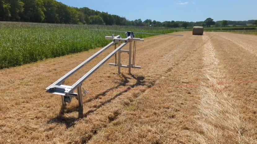
the aircraft) at an angle of 11 degrees. Additionally, the catapult aimed to be as modular as possible. Competition regulations state the catapult had to be storable within the custom-designed container, which has maximum dimensions of 1500mm x 600 mm x 600 mm, and points are scored for how quickly the team can bring the UAS from a point where it is stored to a point where it is operational in the competition. Therefore, a modular, easily stored, and assembled catapult was desirable.
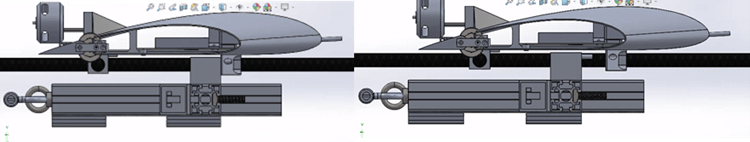
The full assembly for the launch catapult is shown in Figure 1:
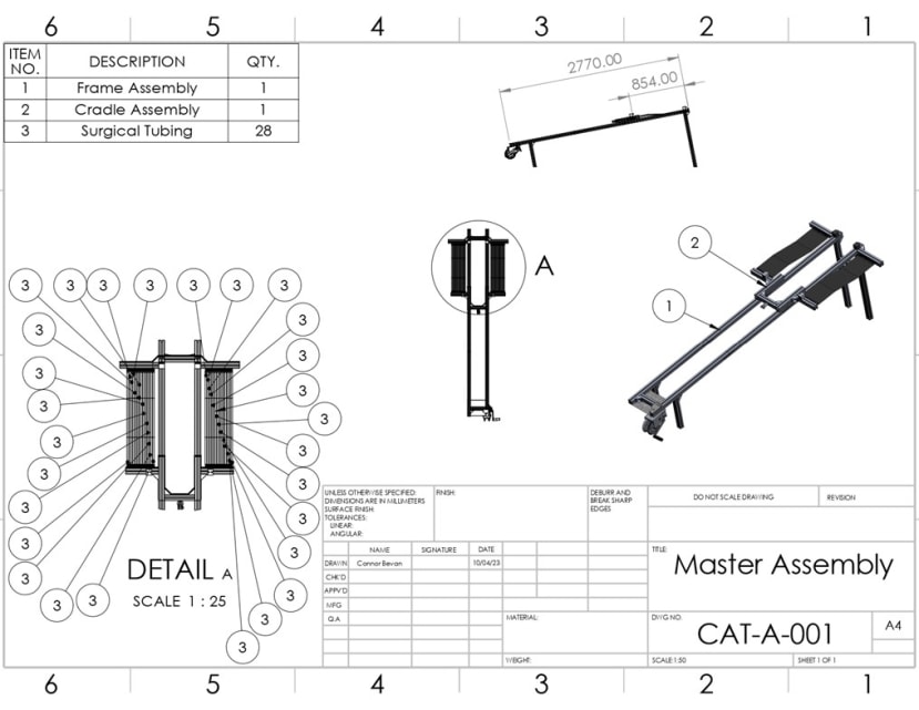
Figure 1 - Launch Catapult Master Assembly
The designed launch catapult consisted of three sub-systems: The frame, the cradle, and the propulsion capability.
Frame
Early in the project, three 2m lengths, two 1m lengths, and one 0.75m length of 45mm strut profile Extruded Aluminium were donated to the project and these were used to form the frame of the launch catapult. There is a wide range of COTS components that are compatible with this strut profile, meaning assembly was very straightforward and the number of bespoke parts was heavily minimised. This made for very reduced lead times and, due to RS stocking many of these components, the RS Grassroots Student Project fund was heavily used to purchase them. The designed frame is shown in Figure 2:
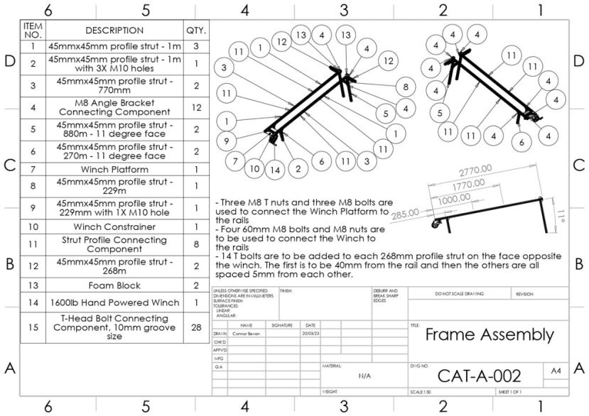
The frame is made up of two 2.77m rails which are angled at 11 degrees by two smaller legs and two longer legs. Each rail is made up of two 1m lengths of extruded Aluminium and one 770mm length of extruded Aluminium. Each profile is joined using COTS strut connecting components that require an Allen key to assemble. This resulted in each length being storable in the container and easy and quick to join when the assembly process begins. From research into COTS Launch Catapults, it was found that 11 degrees is the industry standard inclination for Unmanned Aircraft Launch Catapults. Both sets of legs have had a single-end face cut to this angle to give the launcher this inclination. Two 0.229m pieces of extruded aluminium are used to connect the two rails together. Ten M8 Angle Bracket Connecting Components were purchased using the RS Student Project Fund with the purpose of holding the Aluminium struts together.
At the low end of the catapult, a hand winch was mounted to facilitate the drawing back of the cradle along the rails. Two bespoke parts made from Galvanised Steel were produced to facilitate the binding of the winch in place.
The Winch Platform is connected to the rails via three T nuts profiled to match the 10mm groove in the extruded Aluminium. Holes that aligned with the hole configuration on the hand winch were drilled in the 1m piece of extruded Aluminium, the 229mm piece of extruded Aluminium, the Winch Platform, and the Winch Constrainer. This allowed the winch to be connected by four 60mm M8 bolts and four M8 nuts.
At the other end, two 295mm pieces of extruded Aluminium were added on either side of the rails to facilitate connection with the elastic cord. These two pieces were made from a 2-metre length of extruded Aluminium that was purchased using the RS Grassroots Student Project Fund, rather than the pieces that were donated to the project by the university. Two 40mmx45mmx45mm pieces of foam were added and supported by two more M8 Angle Bracket Connecting Components.
Cradle
Two concepts for a cradle were devised but, following FEA of both, it was settled that the one again made from a 45mmx45mm strut of extruded Aluminium would be used in the final design. The assembly drawing is shown in Figure 3:
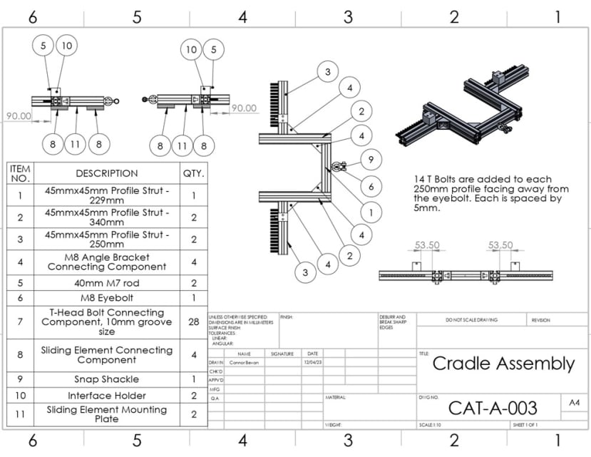
The use of Bracket Connecting Components compatible with this Aluminium strut profile was proposed to hold pieces of extruded Aluminium together. The concept featured a length of extruded Aluminium on each side to facilitate connection with the surgical tubing and an eyebolt on the back to facilitate connection with the hand winch. The aircraft interfaces with the cradle via the part shown in Figure 4:
The aircraft skids are designed with 7mm holes that slot onto the rods on the interface. The cradle would then collide with the M8 Bracket Connecting Components on the end of the catapult the aircraft will de-interface and begin its flight.
Propulsion Capability
The cradle aimed to slide on the rails with minimal friction due to the fact the sliding elements had been profiled to match the groove in the extruded Aluminium. 14 M8 T-bolts were added to each of the 295mm struts of extruded Aluminium at the high end of the catapult.
The T Bolts were, again, profiled to match the 10mm groove in the extruded Aluminium. Following detailed testing of two materials, Surgical Tubing was selected as the elastic material to propel the cradle along the rails. To connect the surgical tubing lengths, it was suggested that the internal diameter of each length could be stretched over each of the M8 T bolts for approximately 10mm. A series of mini clamps were obtained to secure the tubing to each T Bolt.
Between the hook of the winch and the eyebolt on the back of the cradle, the snap shackle was purchased to facilitate the release of the cradle. Release of the cradle would occur once the pin was pulled out.