The Designs and Implementation of a Self-powered Water Smart Meter
Follow project Dave from DesignSpark
How do you feel about this article? Help us to provide better content for you.
Dave from DesignSpark
Thank you! Your feedback has been received.
Dave from DesignSpark
There was a problem submitting your feedback, please try again later.
Dave from DesignSpark
What do you think of this article?
 This project is the design and build of a prototype of a self-powered smart water meter for my university degree. This project focuses on using renewable energy on a small scale to power a smart meter.
Parts list
| Qty | Product | Part number | |
|---|---|---|---|
| 1 | G1&2" Water Flow Sensor Enclosure from Cool compoments | SKU 3522 | |
| 1 | Micro Water Turbine - Hydroelectric Generator (DC-12V) with G1/2'' Thread from Cool Components | SKU 3681 | |
| 1 | 16X2 LCD display with header pins pre-soldered from eBay | N/A | |
| 1 | Arduino, Uno Rev 3 SMD | 7697409 | |
| 3 | SAD-101, Breadboard Solderless Breadboard 83 x 52 x 9mm | 1892277 | |
| 1 | Duracell 150mAh NiMH 9V Rechargeable Battery | 4725517 | |
| 1 | MIKROE-513, 10 piece Breadboard Jumper Wire Kit | 7916463 | |
| 2 | Bourns 10kΩ Rotary Potentiometer 1-Gang, Panel Mount (Through Hole), 3310P-001-103L | 6916885 | |
| 1 | Texas Instruments, 1.2 → 37 V Linear Voltage Regulator, 1.5A, 1-Channel, Adjustable 3-Pin, TO-220 LM317T/NOPB | 5338209 | |
| 1 | Nichicon 100nF Electrolytic Capacitor 50V dc, Through Hole - UVY1H0R1MDD | 8624146 | |
| 1 | Nichicon 10μF Electrolytic Capacitor 450V dc, Through Hole - ULD2W100MPD1TD | 8508436 | |
| 2 | Vishay 50V 1A, Diode, 2-Pin DO-204AL 1N4001-E3/54 | 6288931 | |
| 1 | RS PRO 220Ω Carbon Film Resistor 0.5W ±5% | 738-2699 | |
| 1 | Takachi Electric Industrial Plug in 9V Battery Contact | 1756071 | |
| 1 | 1meter PVC clear tube (18mm diameter) from eBay | N/A | |
The project ahead is the design and build of a prototype of a self-powered smart meter for fluid metering. This project focuses on using renewable energy on a small scale to power a smart meter. The circuit will use the flow of water to power the smart meter and charge a battery. The battery will power the smart meter when the water flow is low. The power would be generated by a micro-hydro turbine generator and the water flow will be measured by a water flow sensor.
First, the charging circuit was designed and simulated on OrCad Pspice and then built. The circuit schematic can be seen in the image below.
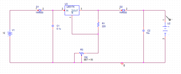
The V1 on the design represents the micro-hydro turbine generator. The generator used has an output voltage range from 0V to 12V. This range was simulated into the charging circuit to determine how much voltage would be supplied to the battery. From the simulation, it was determined that the amount of voltage being supplied to the battery was 7.5V. The U2 represents the Ardunio board and battery. The charging circuit was then built onto a solderless breadboard. The simulation can be seen below.

Next, the water flow sensor and the micro-hydro turbine generator were connected together with the use of the pipe. The water flow sensor was connected to the Arduino board. The sensor was connected to the 5V, digital 3 pin and the ground. The micro-hydro turbine generator was connected to the power rail of the charging circuit and the ground rail.
Next, a 16x2 LCD screen was interfaced to the Arduino board. A potentiometer was used so the contrast of the screen can be adjusted. This was also built onto a solderless breadboard and connected to the charging circuit via the power and ground rails. The full circuit build can be seen in the image below.

The code for the Arduino was then developed. The code takes the pulses from the flow sensor and estimates the flow rate and the volume of water passed through the sensor. The full code can be found in the project.
The code was then uploaded to the board and the circuit was then tested. The pipe was placed onto a tap and the water was turned on. After adjusting the order of the flow sensor and micro-hydro turbine generator, the circuit performed successfully.