Texas Instruments TM4C LaunchPad - Sample I2C traffic
Follow article Dave from DesignSpark
How do you feel about this article? Help us to provide better content for you.
Dave from DesignSpark
Thank you! Your feedback has been received.
Dave from DesignSpark
There was a problem submitting your feedback, please try again later.
Dave from DesignSpark
What do you think of this article?
I have a new LaunchPad, the TM4C Series Crypto Connected. It's the first time that I'm working with this controller family and with TivaWare. I've defined a learning path for @self.
In my previous post, I ended with a design that reads the temperature of an object. The thermometer is the TMP006 (an infrared temperature sensor) from a SensorHub BoosterPack. It talks I2C to the TM4C microcontroller on the LaunchPad.
In this post, I sniff that I2C traffic that's going back and forth between the LaunchPad and BoosterPack.
SensorHub BoosterPack I2C
The I2C traffic in this is using the PD1 and PD0. That's because these two are the I2C data and clock signals for the BoosterPack 1 slot on the LaunchPad. The extract from the Quick Start Guide below shows the relevant pins.

We will connect a logic analyzer to these pins. And then we'll run the firmware and tap off the traffic.
We can then use the protocol decoders of our analyzer to show the data going back and forth IC and µC.
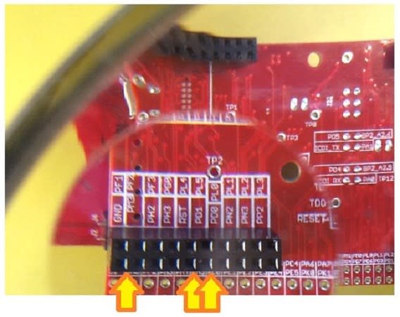
On the image below you can check where the infrared temperature sensor IC is located on the BoosterPack, and where you can find the I2C data and clock pins.

On the LaunchPad, you find the corresponding pins back on connector X9. The easiest way to access the signals is from the backside of the LaunchPad. Connect the probes of your logic analyzer to the ground, PD0 and PD1 pins on the female part of X9.
Probing and Decoding
At this point you should have the LaunchPad programmed with the temperature_tmp006 example from Code Composer Studio's Resource Explorer. Check my previous blog for instructions. And you should have mounted the BoosterPack as shown in the picture below.

Your logic analyzer probes are now attached on X11 ground, PD1 and PD0.
PD0 is the I2C clock, PD1 is the data line. The easiest way to trigger a stream of communication is to trigger your logic analyzer on the clock line going low.
You may have a real time protocol analyzer. In that case you can follow along on screen what's happening. Mine isn't real time. I first have to capture a sample. Then I can use an I2C protocol decoder to make the data visible.
The datasheet of the TMP006 describes the I2C protocol specifics for this IC.

It would be nice if the data that we capture matches the documentation. And it does!
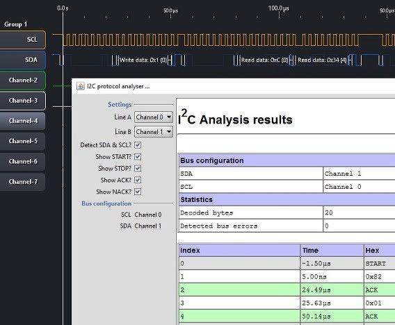
Here's a capture of a write command to the IC:

The first thing the µC sends to the I2C bus is the value 0X82. In bynary that is 0b10000010.
Let's check the manual. It says that the first thing we send to the IC is a 7-bit address, and a R/W bit.
In our case, the address used by the µC is 0b1000001 and the R/W is 0b0.
So if our BoosterPack has wired up the IC as option 2 in the address table (and yes, it does), the TMP006 will listen to traffic addressed to 0b1000001.

Our 8th bit is a 0. We're setting the IC in write mode. It will interprete the next values as a write command. In this case, it's expecting a Pointer Register Byte. It's a pointer to the register that we'll use.
We're sending a 0x01, so we're addressing the IC's local temperature register.

We then send a 0X83. That's again the IC's address, but then with the R/W set to Read. And we get the reply 0X0C 0X34 back (the most significant byte first, then the least significant one), followed by a NACK. Our I2C sequence is complete.

0x0C34 is 0b1100 0011 0100, a 16 bit value. If we turn to the datasheet again. We'll see that register 0x01 contains a 14 bit value, and that the last two bits are to be ignored.
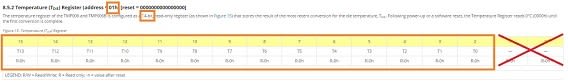
So the real value we're retrieving is the first 14 bits, 0b1100001101.
Check the TivaWare source sensorlib\tmp006.c for the TMP006DataRead(), TMP006DataTemperatureGetRaw() and TMP006DataTemperatureGetFloat() functions to see how we can turn this into the temperature of the object we're measuring.
The easiest way to do this, is to put a breakpoint in your firmware at line
TMP006DataTemperatureGetFloat(&g_sTMP006Inst, &fAmbient, &fObject);
When your debugger stops at that line, first step into that function to see what's happening at the I2C driver level (you will recognize the values from this blog).
Then step over the next lines to see how the ambient temperature and that of the object's surface are calculated from that I2C traffic.
Happy debugging!
Related video:
Probe I2C between TM4C LaunchPad and SensorHub BoosterPack