Surveillance Robot Microcontroller
Follow project Dave from DesignSpark
How do you feel about this article? Help us to provide better content for you.
Dave from DesignSpark
Thank you! Your feedback has been received.
Dave from DesignSpark
There was a problem submitting your feedback, please try again later.
Dave from DesignSpark
What do you think of this article?
 The use of surveillance devices is constantly increasing for residential purposes, while companies and small businesses have been using them for several years.
Parts list
| Qty | Product | Part number | |
|---|---|---|---|
| 1 | Microchip PIC16F877A-I/P, 8bit PIC Microcontroller, PIC16F, 20MHz, 14.3 kB, 256 B Flash, 40-Pin PDIP | 467-1690 | |
| 2 | GP2Y0A21YK0F Sharp, Reflective Optical Sensor | 178-7437 | |
| 1 | Mini 180 Degree Resin Gear Servo SG90 | 215-3180 | |
| 1 | Microchip PICDEM 2 Plus Demo Board | DM163022-1 | |
The aim of the project was to design a surveillance robot, which can be also controlled manually by the user, for instance, the security guard of a company. Therefore, the robot will have two modalities:
- Automatic mode: The robot will be seeking a potential danger, and it will track once detected.
- Manual mode: The user will be able to control the robot with the use of a joystick.
This project was developed with the PIC16F877A (467-1690) microcontroller and MPLAB IDE program.
The project can be divided into two main sections:
- Hardware design: It is based on PIC16F877A microcontroller and different sensors and actuators.
- Software design: Configuration of the modules, inputs and outputs, and the design of the program itself with the help of block diagrams and MPLAB IDE.
HARDWARE DESIGN
1. Equipment
1.1. Infrared sensors
For the detection of the presence of a danger, two Sharp GP2Y0A21YK0F (178-7437) sensors were used. They are analog sensors, but they are used as if they were digital sensors. However, due to the laboratory conditions, in the program that we have designed we select a threshold output voltage from which the robot will assume that a danger has been detected. Below that value, it will be considered that no danger has been detected. As shown in the figure, it does not only mean that we are going to limit the largest distance at which the robot can detect and object, but also de lowest distance.

The implementation of two sensors allows the tracking of the danger. The idea is that when something is detected, the robot is going to try to align the sensors in such a way that both will be detecting that object. For instance, if the sensor located at the right detects something, the motor must rotate to the right, so that both sensors point at the danger. Therefore, if the object is moving, the robot will be constantly readjusting its position, and in this way, the tracking of the object will be achieved.

1.2. Servomotor
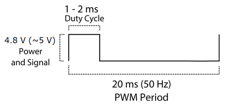
The infrared sensors are the devices designed to read the information of the surrounding area, while the motor will be in charge of the motion of the robot so that the tracking is successfully achieved. A Micro Servo SG90 (215-3180) servomotor was used, which has a period of 20 ms.

This kind of motor allows you to control the position of the shaft, not the velocity of the rotation. For that purpose, we must control the duty cycle of a PWM signal. The period is, as mentioned before, 20 ms, and tON is the parameter that will be modified depending on the position that is required in each moment. These motors can rotate from 0º to 180º, and they typically correspond to a tON of 1 ms and 2 ms, respectively.
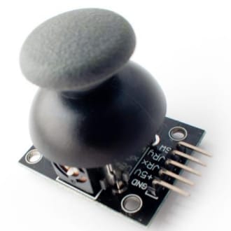
1.3. Joystick
In the manual mode, the user will be capable of using the joystick to control the robot. The joystick consists of two potentiometers. As a result, it can be controlled by the movement of two axis that we will call axis x and y. As we only wanted the robot to be able to rotate around one axis, we only needed one of the potentiometers of the joystick. In addition, it has a button, which is a digital input, that we use to switch on the laser.
1.4. Laser
The laser was implemented to point at the danger in case of the automatic mode and to be switched on and off by the user in case of the manual mode. It simulates turning on and off a spotlight or shooting of a weapon, depending on the purpose that the device will have in its destination.

2. Circuit connections
The hardware design finishes once all the connections are properly made. We have to connect the sensors and actuators to the microcontroller so that it is able to communicate with them and collect and transmit information. Besides, the microcontroller must know which pins are outputs and which ones are inputs, consequently, we must configure their corresponding register. However, this will be explained in the software design section.

SOFTWARE DESIGN
1. Main program
First, we must configure all the modules and ports that we will use. Then we will start programing. It is a good idea to draw some block diagrams to organize better the ideas.

1.1. Automatic mode
The program will be divided into the two modalities that have been explained already. With respect to the automatic mode, as the sensors are connected to the terminals RA2 and RA3 (see connections), in other words, to the channels 2 and 3; then CHS1=1, and CHS0 will be varying its value. The change in the channel will be performed at the end of this section of the program. At the bottom of the flux diagram, there is a red block which indicates that the loop is closed, and that it returns to the block in red of the diagram above.

In order to understand better the flux diagram, the variables used must be explained. Variable conv stores the information given by the A/D converter. In this case, the information is provided by the infrared sensors to the converter. As mentioned before, those sensors are not digital, and we are going to limit their range due to laboratory conditions. The value of conv=100 was achieved experimentally which corresponds to an output voltage of 0.5 V, approximately. Consequently, the range is limited to 60 cm.

1.2. Manual mode
Concerning the manual mode, now the converter will be used to read and transmit the information received from the joystick, which corresponds to the channel 1 (CHS0=1 and CHS1=0) or to the terminal RA1.

2. Interruption Service Routine (ISR)

3. Modules used
3.1. CCP1 module
Comparation mode with interruption generation. It is used to control the part of the PWM signal with value ‘HIGH’. The control is carried out with the register CCPR1.
3.2. CCP2 module
Comparation mode with interruption generation, reset of Timer1 and launch of A/D conversion. It is related to the period of the PWM signal which is constant and has a value of 20 ms. The post divider of Timer1 is 1, as a result, CCPR2 is 20000.

3.3. Timer0 module
It is configured with a pre-divider of 4. It is used to determine the conversion frequency of the A/D converter, whose period will be of 1 ms.

3.4. Timer1 module
It is used in combination with the CCP modules, in comparison mode, to generate the PWM signal. As mentioned previously, the post divider is 1. The register TMR1 is set at 0.
3.5. A/D converter module
It is configured with analog inputs and outputs and justified to the right. Additionally, we want the frequency of the clock of the converter to be Fosc/8.
VIDEO