Student Innovation - 3D printed desktop CNC
Follow article
 Dave from DesignSpark
How do you feel about this article? Help us to provide better content for you.
Dave from DesignSpark
Thank you! Your feedback has been received.
Dave from DesignSpark
There was a problem submitting your feedback, please try again later.
Dave from DesignSpark
What do you think of this article?
Introduction.
Hello. I am Chris and being 16 and in year 11 this summer I should have been taking my GCSEs. However, I didn’t. Earlier this year, the Coronavirus pandemic put an abrupt halt to everything, including school and my exams. When I received this news in March, I thought about what I could do to fill the time whilst learning at home. My fascination with science, technology, engineering and maths lead me to think about a challenging STEM based project to complete in lockdown.
I have been using CAD in conjunction with my 3D printer for 3 years now, designing plastic cases for electronics projects and various other functional parts. During my time learning about additive manufacturing I had often read about subtractive manufacturing using CNC mills and routers to cut a wide range of materials. However, I had always dismissed the possibility of using and owning one due to the high cost associated with buying even a small desktop machine.
I then thought about the possibility of using what I knew about CAD and 3D printing, to create parts for a CNC machine! Designing the CNC mill myself and using 3D printed parts would significantly drive down the cost. This project would give me the opportunity to use various engineering disciplines such as mechanical and electrical. It would also require me to learn about CNC design and Computer Aided Manufacture (CAM). I decided It would be a perfect lockdown project to continue my learning. The following project is the journey I went on to complete my 3D printed desktop CNC.
Design Brief /Specification.
Before completing any design work, I laid out some basic specifications I wanted the machine to conform to. These parameters would help focus my design work and ensure the machine I produced was what I intended it to be. I also wanted to use some parts from an old 3D printer such as the motors and lead screws to cut costs.
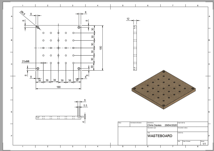
- 180mm x 180mm x 60mm workspace area.
- 500w spindle motor with ER-11 collet.
- Aluminium frame.
- Ability to machine plastics, woods and aluminium.
- Fixed X-axis gantry (movable bed).
- NEMA 17 stepper motors (From 3D printer).
- Use as many parts as possible from an old 3D printer.
- A minimal amount of parts to cut to length (Reduce offcuts and total material wastage).
Initial designs considerations.
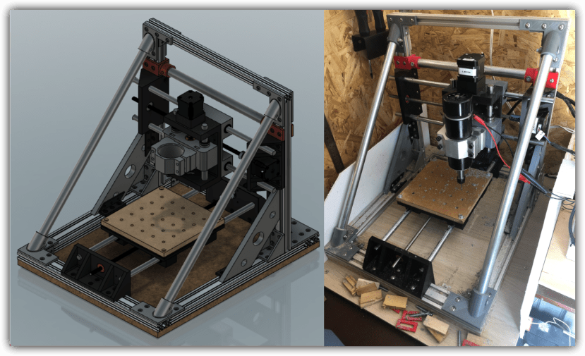
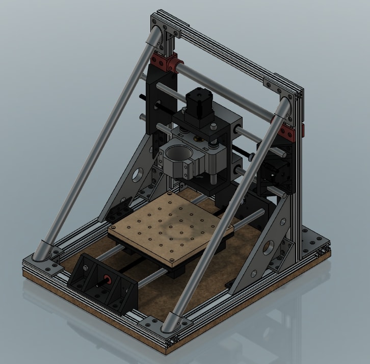
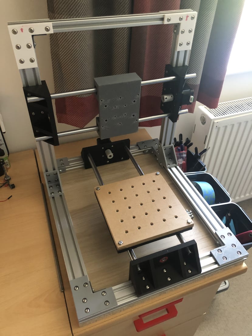
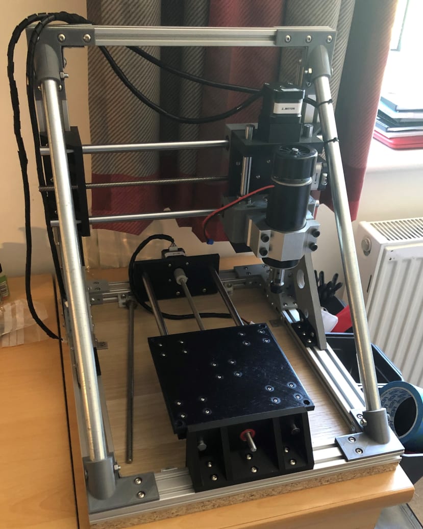
After completing the design brief, I moved into my CAD program (Fusion 360) to start designing the frame. When designing the frame, I had to think about what size to make it in order to achieve 180mm of possible wasteboard movement in the Y-axis direction. The frame would have to be at least 360mm long (180mm x 2) for the bed to move from one extreme to another. The 400mm lengths of 2040 aluminium extrusion I was going to use for the base laid out in a rectangular shape gave me 380mm of Y-axis movement, after factoring in the width of the Y-axis motor bracket. 380mm was 20mm more travel than I needed, which would be a perfect amount in order to reach both ends of the 180mm bed and have some to spare. For the X-axis, I had 300mm of available travel space. This would be more than enough because the width of the Z-axis carriage was less than 150mm (300mm / 2) so it would easily reach both ends of the wasteboard in the X-direction. Here is the final CAD model:
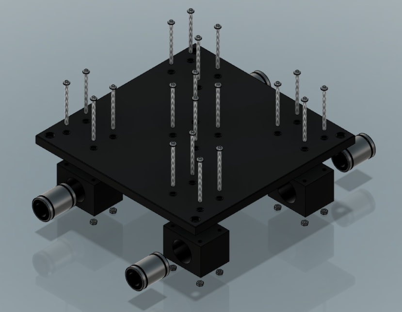
An interesting design feature I incorporated into the base platen of the machine was to print the bearing housing blocks and lead nut housing block separate to the base platen. This design for maintenance feature meant that if one of the bearing housing developed a crack in it, the bed would not need to be reprinted, only the housing. This would reduce the amount of filament wasted if something broke and significantly reduced re-printing time for the part.
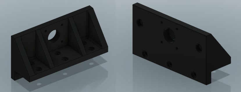
The next consideration was the design of the Y-axis motor brackets. These brackets would provide a fixing point for the two Y-axis linear rails, lead screw and stepper motor. The design I came up with allowed the bracket to fix to both the top and inside face of the aluminium extrusion using nine counterbored holes. These brackets were designed for printability with no support material needed as they could be printed face down. I used a similar design for the X-axis motor mounts, only making the distance between the locating holes for the linear rails smaller to give me more flexibility when moving on to designing the Z-axis carriage.
When designing the CNC, I knew that I needed a wasteboard on top of the platen that stock material could be fixed to for machining. I had a piece of 12mm thick Medium Density Fibreboard (MDF) and decided to use M6 threaded inserts to create a threaded wasteboard. This would remove the need for me use screws to secure the material to the wasteboard before each cut making it look nicer for longer.
3D printing the parts.
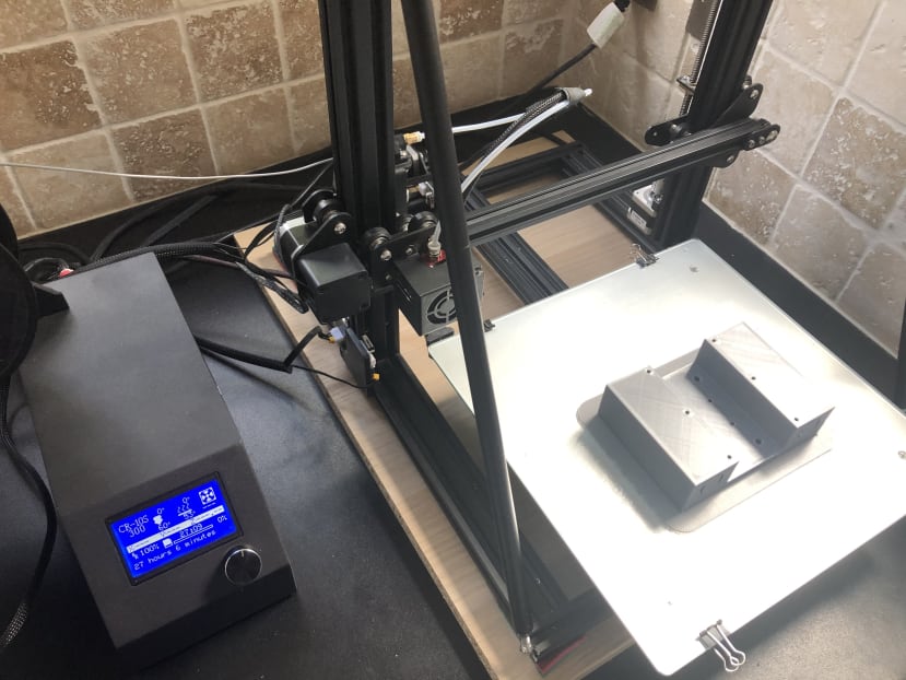
Once I was happy with the final iterations of the parts in CAD I started to print them on my Creality CR-10s 3D printer. I used black, grey and red PLA filament for the prints. It took a week and 1.5kg of filament to complete all the prints, the longest single print being 27 hours! The print settings I was using were:
- Print speed – 50mm/s
- Layer height – 0.2mm
- Infill – 60%
- Nozzle temperature – 210°c
- Bed temperature – 60°c
Building the machine.
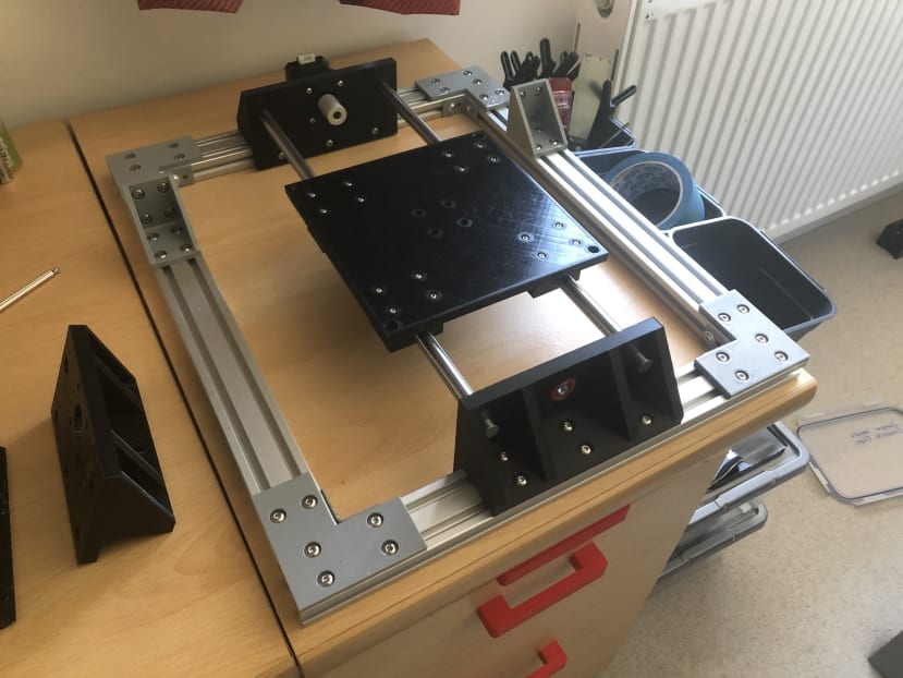
- I started by assembling the base of the machine using four 400mm 2040 aluminium extrusions. For the build, I used 6, 8 and 12mm M5 pan head bolts. For the nuts, instead of using aluminium extrusion nuts, I used standard square nuts. These fitted perfectly into the channel of the aluminium extrusion and were much cheaper than extrusion nuts. This also helped to cut the cost of the machine.
- Next, I fitted both Y-axis motor brackets to the base frame of the machine using 12mm M5 bolts. After the brackets were installed, I pushed the printed platen onto 12mm linear rails and pushed the linear rails into the locating holes on the Y-axis bracket. Then I fitted the Y-axis motor, lead screw and ball bearing to the machine.
- After completing the Y-axis, I turned my attention to the X and Z axis. The fixed X-axis gantry is similar in design the lower Y-axis gantry. From the CAD design, I knew the position along the base frame at which the X-axis gantry would need to sit for the spindle to be directly over the end of the bed when the bed was all the way forward or back.
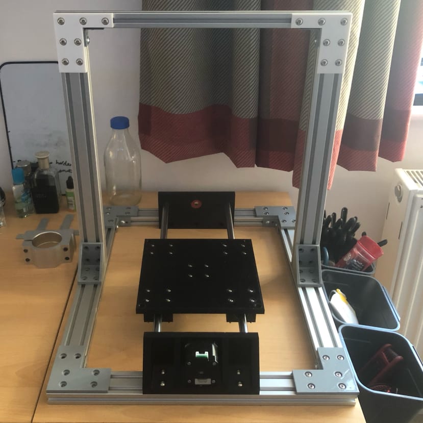
- Next, I fitted the two X-axis brackets to the X-axis gantry. I then pushed the back piece of the Z-axis carriage onto the X-axis linear rails of the machine and installed the threaded wasteboard.
- After that, I installed the front piece of the Z-axis carriage.
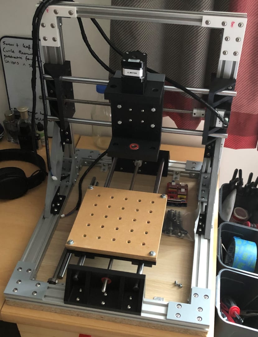
- The linear rails and lead screw for the Z-axis were the only parts that needed cutting to size. This met the criteria of my brief which stated, ‘minimal amount of parts to cut to length’. I then Installed the Z-axis stepper and spindle mount to the Z-axis carriage.
- Finally, the spindle motor was installed.
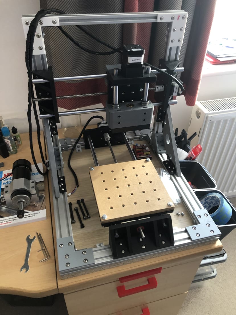
Electronics
For the electronics, I used the stepper motors from my old 3D printer. The stepper motors are NEMA 17 stepper motors. When designing the machine, I debated whether NEMA 17 stepper motors would be strong enough to cut through harder material mentioned in my brief such as aluminium. I decided the NEMA 17’s from my old printer should have a high enough dynamic torque for milling softer materials and harder woods, plastics and metals when using conservative feed and speed rates.
For the control board of the machine, I used an Arduino Uno with a CNC shield. This allowed me to use the A4988 stepper motor driver module to control the speed and direction of the stepper motors on all three axes. I used the open-source CNC milling controller, grbl for motion control of the CNC.
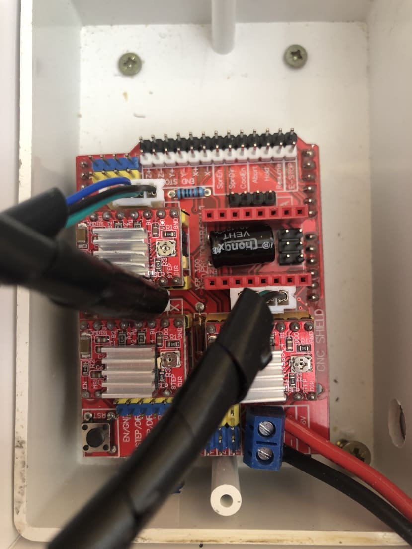
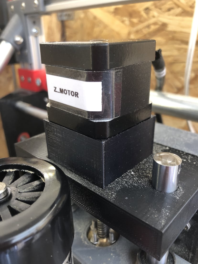
I used microstepping on the CNC which gave me an excellent motor shaft resolution for machining small, intricate shapes and patterns. To enable microstepping on the control board I used header jumper pins to connect the two male header pins under the stepper motor driver.
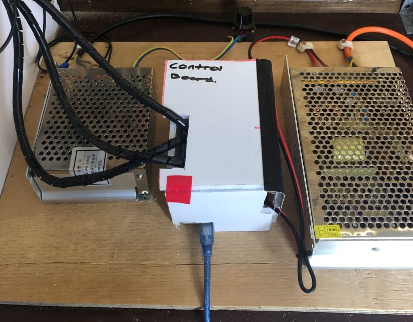
For power, I used the power supply from my old 3D printer. The power supply is overkill for the job because it is only powering three stepper motors which draw around 5A max. However, the PSU is rated at 20A max.
The spindle motor is controlled by a separate power supply unit that uses a potentiometer to control the spindle speed up to 12,000 RPM.
Once the machine was completed mechanically and electrically, I began to learn about using CAM to generate toolpaths and G-code to send to the machine. For the G-code sender, I used CNCjs.
Initial tests.
I ran some initial tests by manually sending G-code commands to move the machine about. When I ran some initial tests I found the X-axis and Z-axis were inverted. This caused me a problem, but I found a PDF online that contained a useful table which showed you which commands to enter to flip the axes (linked at the end of the article). For me, I just had to type $3 = 5 into the console of CNCjs and the axes were then inverted!
Workflow.

Upgraded design features.
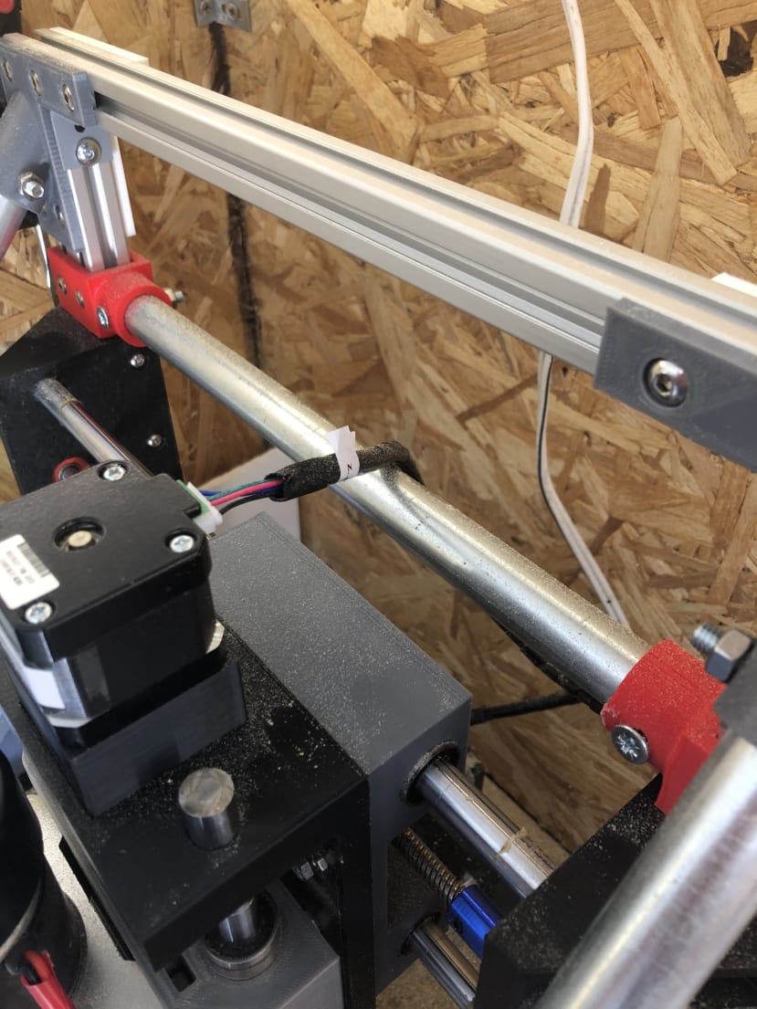
After running some initial tests, I noticed some slight play at the top of the axis gantry. I needed to fix this to stop any unwanted movement whilst cutting stock material which could lead to inaccuracies in the part, machine damage and snapped endmills.
To combat this, I used some 20mm steel tube I had to make some support bars for the X-axis gantry. I once again used CAD to design some upgraded mounts that could be fitted around the pipe and fixed to the base frame.
I also added an extra strut bar between the two upright sections of extrusion on the X-axis to help brace the machine and limit any unwanted movement. Finally, I screwed the base of the machine to a piece of board which was secured to my workbench which also helped to limit movement and dampen vibration. After I made these modifications, I had eliminated any play in the machine which meant it was better at cutting material.
Initially, I used flexible couplings to join the lead screw to the motor shaft. However, I noticed too much unwanted axial movement so I replaced them with rigid couplings. This upgrade helped improve the accuracy of the movement of each of the three axes.
Cutting results.
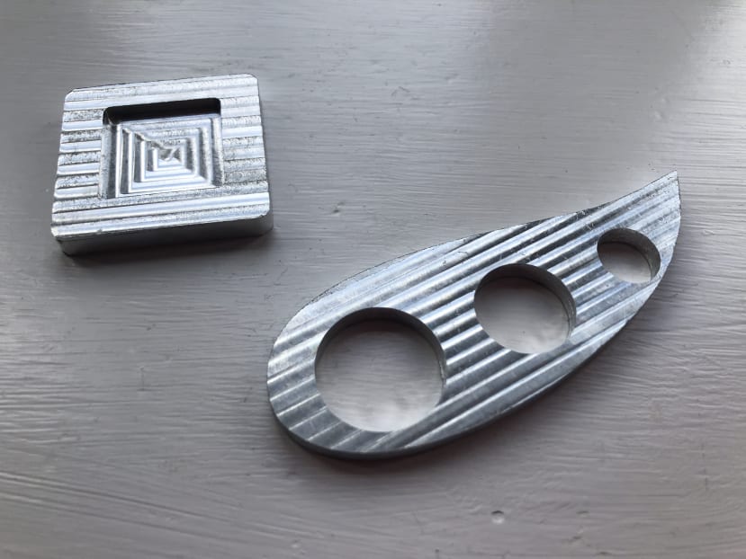
I have been using the machine for some time now and have machined lots of plywood. I also wanted to try to machine some aluminium which was an ambition of mine from the project outset. Machining aluminium would be the ultimate test for my machine’s design, rigidity and components. I set out by slowing down my plywood feeds and speeds to find suitable ones for aluminium. After trialling a few different feeds and speeds I managed to machine a piece of 6mm thick aluminium bar!
I used a depth of cut of 0.1mm and feed rate of 400mm/min and have achieved results that look almost like a mirror. Here are the results:
Here are the plywood cuts results:

Conclusion.
In conclusion, my CNC project has proved a success. I have met all of my initial design brief points. The CNC has helped me to improve my CAD skills as designing the parts for the machine took many hours and required me to use features that I had not previously used inside of the CAD software. The project also required me to overcome various challenges along the way from re-printing incorrectly sized brackets to removing incorrectly aligned linear bearings from bearing blocks.
The project has also taught me about the basics of CAM which initially looked daunting due to the large number of available tick boxes and settings to adjust. However, after persevering, I overcame the challenge which resulted in high quality machined parts in materials such as plywood and aluminium.
Traditionally, CNC mills are made from rigid materials. However, I used the materials and resources I had available to build my own CNC and produce stunning results.
Next steps.
I plan to continue to use my 3D printed CNC to machine more materials such as copper clad PCBs and plastics. I also aim to machine more designs using other operations within my CAM package to produce more complex parts.
I would also like to add more of an enclosure to my CNC which will help with the containment of chips and swarf when milling because if CNC milling has taught me anything it is that it’s a messy process!
Useful links.
CNCjs - https://cnc.js.org/
Grbl - https://cnc.js.org/
Grbl commands PDF
- http://www.diymachining.com/downloads/GRBL_Settings_Pocket_Guide_Rev_B.pdf
Instagram - Follow my instagram for regular update about my CNC and other projects I am working on: cd_technologies