Spur into action with ContinuumBridge interactive buttons
Follow article Dave from DesignSpark
How do you feel about this article? Help us to provide better content for you.
Dave from DesignSpark
Thank you! Your feedback has been received.
Dave from DesignSpark
There was a problem submitting your feedback, please try again later.
Dave from DesignSpark
What do you think of this article?
Following on from GreigRS’s excellent article on the deployment of the ContinuumBridge Spur call to action buttons at RS Nuneaton distribution centre, we’re going to take a dive into how to register and program a button to get useful calls to action and data back from button presses.

With this sort of process optimisation and workflow automation, it’s easy to see an immediate return on investment (ROI) e.g. replenishment man hours, packaging downtime, predictive motor maintenance. But it’s also easy to miss two factors that boost that ROI:
- It’s people that define, manage and man these processes.
The proof of concept at RS has taken input and been refined by all these people.
Many companies are now realising that the Industrial IoT is as much about interactions with people as it is about the inevitable sensors and actuators. This may be as complex as a hyper-intelligent service manual, or as in our case, by simply pressing a button – and getting a response on the screen from a machine e.g. “Your order has been placed. Delivery on 2nd Feb”, or from a human: “thanks, be there in 5mins”.
- The real insights and key questions come from the data:
- Why does Sector K have so many callouts?
- Service provider X isn’t meeting its service level agreement in these ways.
Let’s get started...
Prerequisites
You’ll need an account on portal.spur.site, a Bridge and at least one Spur button. If you don’t have an account then please contact your ContinuumBridge representative.
You’ll also need mobile network coverage (3G). There is also provision for an Ethernet connection. Note that this will make the Bridge visible on your network and, depending on your firewall, maybe the internet. The Bridge is secured but clearly more open to attacks when connected this way.
Definitions
Bridge: essentially the gateway between many buttons and the ContinuumBridge servers. The Bridge also functions as an edge computing device running “services” that talk to various sensors and actuators as well as Spur buttons. This way we can send only interesting and useful information to the cloud. The Bridge is designed to be always-on and always connected.
Spur Portal: portal.spur.site - a website from which you can register and program your Spur buttons, and view dashboards.
Organisation: As a user on the portal, you will belong to an organisation.
Your Lists, Screensets (and consequently your Bridge and Buttons) will also belong to this organisation. Different Organisations are private from one another.
List: Lists are used to group together buttons of a similar function (or indeed location). In the example below, there are functional lists for “Cleaning”, “Packing Bays” and “Recycling”.
Screenset: this is a flow chart state machine that defines what text appears on the screen in each state and what state transitions and actions occur on various types of button press. Multiple buttons can have the same screenset whilst sending their alerts to different destinations. Screensets are created and edited using an intuitive online graphical editor. Changes to a screenset are automatically pushed to all buttons using that screenset.
Getting started - 5 easy steps
1. Decide where to put your Bridge and power it up.
The range of the bridge to button wireless interface is about 300m in the open air and building penetration is good. So the location of the bridge isn’t that important in a large office. If you have several buttons dotted around then try to place the bridge somewhere central - about equidistant from them all. In very large spaces like the RS warehouse, you may need more than one bridge. We’ll cover this scenario in a later article.
Plug your Bridge into a power outlet. After a short time, the red LED will begin flashing and eventually become solid indicating that the Bridge has connected to the servers. This could take several minutes, particularly the first time.
The bridge is intended to be permanently powered-up as Spur buttons can be pressed at any time of day (and they check in periodically). This also ensures that your Bridge will receive software updates.
2. Log in to the portal
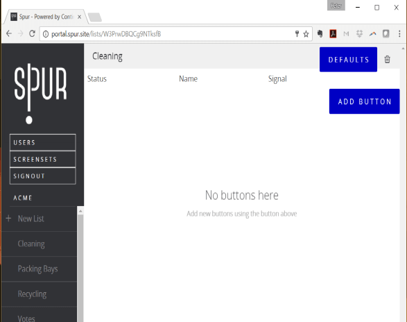
In a web browser navigate to portal.spur.site and enter your username and password. You’ll see a screen similar to the one below. Here we can see that the Organisation ACME has several Lists of buttons. We can also see that there are no Buttons in the “Cleaning” List.
3. Create a screenset
There is plenty of documentation about screensets on the Spur portal so for brevity here, we’ll walk through the “Replenishment” screenset in use at RS in Nuneaton. This demonstrates many of the functions available.

Referring to the screenset above:
When started, the button moves to the first state and displays: ”Push here if this pallet needs replenishing”. Note that the * (stars) make the text on the button bold and the green “LED” in the bottom right will light a green “ok” LED on the Spur dashboard. The connectors on the right and left of the screen are the exit points for left and right single press (top pair) and left and right double press (bottom). In this case, we’re using any single press to take us to the next state (the lines are a bit difficult to see – they don’t connect to the bottom connectors).
So any single press takes us to the next state “Replenishment Requested” via an SMS alert box. The SMS message is sent to the phone number as we enter the “replenishment requested” state. In this state, we see an orange light on the dashboard (and a bell rings).
The defined workflow is that after replenishing the pallet, the replenisher double presses the button to clear the work order. So we see connections from the bottom left and right connectors back to the first state i.e. a double press on either side.
A second part of the workflow allows the callout to be escalated if it isn’t cleared within a time limit (64800 seconds in this case – for testing I suggest you use 10 seconds!). There are various ways of implementing timers in screensets – here we have used an email alert box with the keyword #delay. After the fixed delay in the message field, this falls through and arrives at the second “replenishment requested” state which shows a red LED on the dashboard (and rings the bell again), and sends an email to the boss. Again, any double press clears the callout and returns us to the first state.
4. Register your button on the portal and program it with your screenset
Your button will have arrived with a screen like the one below. If you don’t see this screen, you can reset the button to this state by pressing (anywhere) for 10 seconds followed by a double right press.
Note that the Node ID of this button is 535. Yours will be different.
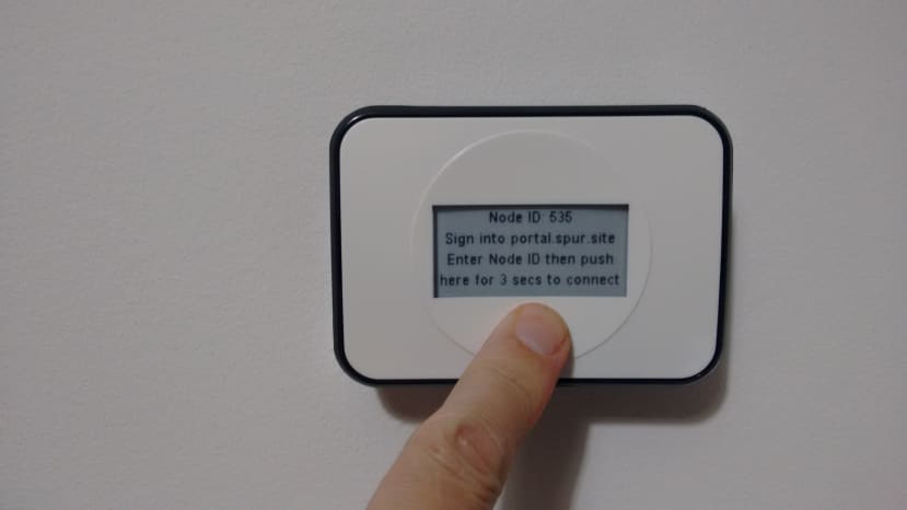

Enter your Node ID and a name. In the Start state, the button displays this name so it’s a good idea to make it descriptive of the intended location as an instruction to the installer.
The email and SMS fields enable different destinations to be assigned to different buttons that use the same screenset – but in this case, we’ve hardwired these in the screenset so can leave them blank here.
Finally, select the screenset you want and click ADD BUTTON.
You’ll now see your button on the portal with a question mark over the signal bars and no status LEDs lit. In other words, the button has been successfully registered but is not yet connected:

5. Connect your button
Now return to your button and follow the on-screen instructions.
After pressing and holding for three seconds the button will display a message saying that it’s connecting to the network and, once connected, it will download its software. Be patient, this process can take a few minutes!
Once complete, the button will display its name and “double push to start”, and the portal will show the signal bars and the LED status (which is green at the start for this screenset):
Congratulations!
Pressing the button will now send an SMS to your chosen number and light an LED and ring a bell on the dashboard. If not cleared within your set period, the callout will escalate and send an escalation email. A double press at any time will clear the callout. All these events are stored and can be accessed for future analysis.
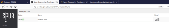
For interest, here is the current status of the pallet replenishment buttons deployed at the RS Nuneaton distribution warehouse. They have one escalated replenishment callout and all buttons have a good signal.

Also on this screenshot, you can see the other use cases that GreigRS referred to along with a few others. The Lists of buttons include:
“TM Sector Calls” – the request for a Team Manager in each of 10 sectors
“Nuneaton Lifts” – asset down, a fault report, calls the engineer
“RS Order” – automatically place an order when stocks are low
“Martins test” – as it says, used for development
In this article, we’ve seen how to program buttons and create useful calls to action via emails and SMS messages and to display these on a dashboard. In the next article, we’ll look at the API and how this integrates with Smart Asset and Workforce Management systems.
Find out more at ContinuumBridge