Source and Measure Units unveiled
Follow articleHow do you feel about this article? Help us to provide better content for you.
Thank you! Your feedback has been received.
There was a problem submitting your feedback, please try again later.
What do you think of this article?
Introduction
Keithley has a long experience as a high precision SMU manufacturer and SMU systems integrator. There is a wide range of instruments you can choose, based on your requirements such as measurement range, power constraints, accuracy needed, number of channels.
Among them, I find myself often using the KEI 2461, one of the four Keithley Touchscreen SMUs.
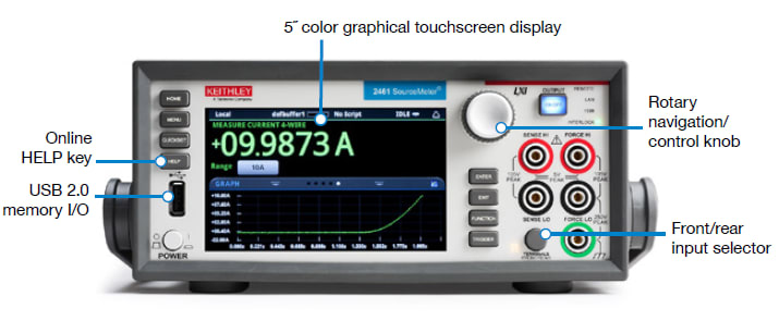
I found it very easy and fast to configure and then see the results with the 5” graphical touchscreen display, but, of course, there’s more than meets the eye.
It’s not just a simple power supply
One very basic use of the SMU could be, for example, as a supply to power up your board and manually tweak the voltage until you discover some issue in your board.
With the “Live Update” feature, you can turn the front panel knob and adjust the output voltage down to 250µV resolution in the 7V range, while measuring the current with 6 digits.
I would like to stress out here the fact that Source Range and Measure Range have different resolutions, as you can see from the specifications on the datasheet below (the same happens with the current)
By lowering the voltage, you can find the operating limits of your board…and…
“Come on, Enrico!!! You invited me just to see what I can do with a simple power supply?”
Well, I will answer with the following pictures below:
Researchers involved in device characterization surely know that an SMU can, for example, create a voltage linear sweep and measure the current while sweeping. This can be used in order to determine the I-V characteristic of a diode (for a single channel SMU like ours) or a transistor (two or more channels SMU). The graphical display of the 2461 (but also 2450, 2460 and 2470) gives you the chance to have a fast overlook of your device under test:
What makes the 2461 more interesting is its pulsing capabilities along with the 1MS/s 18-bit digitizer.
Let me reveal a secret…every Keithley SMU can pulse a signal even without pulsing capabilities. You can write some TSP (Test Script Processor) language code and have your sourcing as a pulse train, but a SMU is not a “time domain” instrument as a function generator.
The SMU sources and measures and, in order to measure, it will add some measuring time at the end of your pulse, as shown in the following picture:
In order to have narrower pulses, you can reduce the measurement time (i.e. use a fixed measurement range, set the NPLC integration to minimum, turning off source delay, etc…), but this will lead you to an imprecise measurement.
If we want to overcome this, we can use the digitizer capabilities of the 2461 and see what we can do in the next paragraph.
Simulating a voltage sag
As said before, physicists and device characterization engineers are aware of the sweeping and pulsing characteristics of the SMUs, so how can the 2461 be useful to a hardware design engineer?
Well, if you have a complex board with FPGAs, DDR memories and microcontrollers, you know that powering up phase requires attention and supervisor circuits like power-on reset circuits or voltage monitoring circuits.
With 2461 you can work in the early stage of your development design and see what happens if a voltage failure occurs by using the pulsing capabilities.
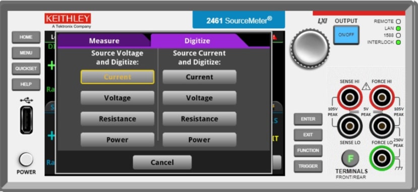
As shown below, you can choose to Source Voltage and Digitize (other than measure) current function:
Pressing now the MENU button, we can go and enter the Measure Settings in order to set the sample rate and the count (i.e. record length of our acquisition):
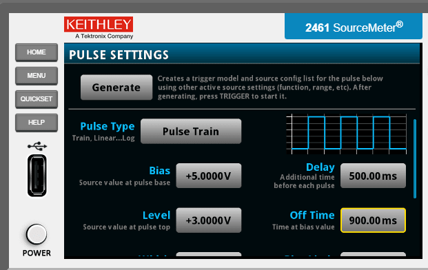
At this point we can create our voltage sag, that is a 1ms voltage drop from 5V to 3V:
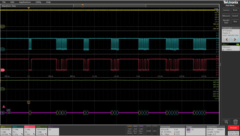
Now we can power up our board and see what happens after the voltage sag, but before let’s have a look to our scope trace to reveal the behaviour of the board:
We used a Tektronix MSO6 to show the following traces:
- Yellow trace 2461 supplied voltage
- Blue and Red traces à SCLK and SDA of the I2C bus
- Green trace 2461 supplied current
- Purple trace a I2C bus decoding
We set the scope to capture several events, including our voltage sag and zoom on it:
We can see from the picture above, that as soon as the voltage drops to 3V (yellow trace), the current starts to drop and become negative (green trace), but the board is still functioning after everything goes back to normal.
And what about our 2461? Well, we can have a look at the digitized current and pinch and zoom on the display to have a deeper look at the sampled current:
As for the scope, the current (supplied by the 2461 itself) became negative and we can read the negative peak relying on the 18-bits 1MS/s digitizer of our SMU.
So now, please, tell me, did I invite you only to show a power supply?


