RF Communication and the Internet of Things - Part 3
Follow articleHow do you feel about this article? Help us to provide better content for you.
Thank you! Your feedback has been received.
There was a problem submitting your feedback, please try again later.
What do you think of this article?
In Part 1 I talked about the calculation of a Link Budget in order to determine the transmitter power and receiver sensitivity required to communicate over a given range. Part 2 showed how noise and interference levels determine the maximum data rate achievable. Now in the third part we’ll look at some of the other interesting jargon phrases such as ‘Data Whitening’ and ‘Spread-Spectrum’ found on wireless chip/module data sheets. All that follows refers to coding of the baseband signal before modulation onto an RF carrier. This stuff may seem a bit nerdy if all you want to do set up a home WiFi system. But should you want to start developing something of your own, then some knowledge of what the jargon means will help you make basic design decisions and avoid buying a lot of useless hardware.
Baseband Signal Bandwidth
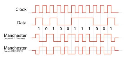
Let’s start with the baseband serial digital data signal. It’s in a Non-Return-to-Zero (NRZ) format where, say, 0 volts represents logic 0 and +5 volts is logic 1 (Fig.1). The data is reasonably random, with any long strings of 1s or 0s accounting for low frequency components in the spectrum with the highest coming from groups of alternating 1s and 0s. The bandwidth of this signal is large because of the harmonics caused by all those sharp rising and falling edges. Fortunately, it can be significantly reduced because we don’t need all those harmonics to reconstruct the waveform at the receiver. It turns out that for two-level signalling the minimum bandwidth required is equal to half the clock rate. The frequency plots included here though, show the ‘double-sided’ frequency spectrum centred on the carrier frequency that results from the modulation process. In other words, for binary signalling the bandwidth of the modulated signal is twice that of the baseband signal.
Data ‘Whitening’
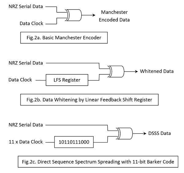
Long strings of 1s or 0s in the baseband signal cause problems at the receiver. The clock synchroniser circuit attempting to recover and track the incoming data clock needs frequent ‘transitions’ in the signal to do so. When very long strings of 1s or 0s are likely to be present in the data, it is usual to ‘randomise’, ‘scramble’ or ‘whiten’ the NRZ signal prior to modulating the carrier. At the receiver, the demodulated signal will then require unscrambling or ‘de-whitening’. A scrambler is usually a form of Linear Feedback Shift Register (LFSR); in practical terms, a shift register with a couple of EXOR gates (Fig.2b).
Predictable Randomiser
A contradiction in terms? Strictly, yes. But the rather obvious fact is: what the scrambler scrambles, the unscrambler has to unscramble! Fortunately, the LFSR circuit implements a piece of mathematics which, when initialised to a particular starting value (the shift register is preloaded with a particular number or ‘key’, usually all 1s), it spits out the same seemingly random sequence each time. It’s called a Pseudorandom sequence because it repeats after an interval determined by the register length. For example, a 15-bit LFSR will repeat after 32767 clock cycles. The unscrambler is identical, but needs some additional circuitry to synchronise it with the scrambler.
Fortunately for the developer, most modern transceiver chips/modules include data whitening hardware. Annoyingly, there is more than one whitening standard and the link designer must make sure that the transmitter and receiver both use the same one. The two most common are the IBM and the CCITT (ITU-T) Whitening standards.
Manchester Encoding
Whitening the baseband signal does not remove all the very low-frequency components however. In order to remove them and any DC level completely and ensure that each bit-interval contains a 0-to-1 or 1-to-0 transition for the purpose of receiver clock recovery, we must turn to some encoding techniques. The most common is called Manchester encoding and consists of replacing each 1 in the NRZ data with a low-to-high transition half way through the bit interval and each 0 with a high-to-low transition (Fig.1). Notice all the short pulses introduced providing a data transition in the middle of every bit period. As every bit interval now contains a transition, the DC component of the original NRZ signal is eliminated.
No Free-Lunches
The price for more reliable data clock recovery is a doubling of the baseband signal bandwidth when Manchester encoding is used. The transmit hardware required is very simple and basically consists of a 2-input EXOR gate combining the data clock with the NRZ data, outputting the encoded stream ready for modulation of the carrier (Fig.2a). At the receiver the demodulated signal is EXORed with the recovered data clock yielding the original NRZ data. As with Whitening there are a number of different coding schemes in existence including an inverted form of the Manchester. The form described here complies with the IEEE 802.3 convention; the ‘inverted’ form is the original invented in the 1940’s at Manchester University for use on computer drum storage drives. Note that it’s usual to use Data Whitening or Manchester Encoding but not both at the same time!
Cyclic Redundancy Checksum (CRC)
On the subject of coding, most packet-based communication protocols use a simple process to calculate a check-word from the ‘payload’ data in each packet. The check-word is appended to the end of the payload. The receiver circuits perform the same calculation on the incoming payload and the check-word. The result should be zero if no errors are detected. The CRC generator and check circuits are identical and once again just consist of shift registers and EXOR gates. Most transceiver chips or modules with packet handling will have the necessary hardware for CRC generation and checking. An error usually triggers a re-send packet request to the transmitter. There are many versions of the CRC algorithm: one of the most common is called CRC-16 and, unsurprisingly it generates 16-bit check-words. As with Whitening, the same algorithm must be used at each end of the wireless link.
Forward Error Correction (FEC)
Most wireless devices will generate/check a CRC, but its use can result in a significant number of retries in a noisy environment, particularly with long data packets. An alternative sometimes provided is Forward Error Correction where extra code bits are added throughout the packet. The receiver can use these to correct errors without having to request re-transmission. A particular coding scheme is usually defined by its Code Rate k/n where n is the total length of a block including k data bits and n-k redundant code bits. Obviously the greater the proportion of code bits in a message, the better the error detection/correction. But the useful data throughput will be reduced.
Spread Spectrum Techniques
So far we have looked at some simple baseband coding techniques which help to make communication between a single transmitter and a receiver more reliable. Such a system might be remote central locking for a car or remote garage door control. Expansion of the Internet of Things will involve a vast number of interconnected wireless systems crowding into the limited so called ‘license-free’ frequency bands known as Industrial, Scientific and Medical or ISM bands. In the short-range 2.4GHz band, you will find WiFi, Bluetooth, DECT phones and even microwave ovens. The 868 and 434MHz (‘Sub-1GHz’) bands more suited to longer range communication are filling up fast as low data-rate networks such as Sigfox™ and others using LoRaWAN™ are established. In order to improve the performance of wireless systems in this free-for-all environment two techniques are now widely used: Frequency Hopping Spread Spectrum (FHSS) and Direct Sequence Spread Spectrum (DSSS) with a third, Chirp Spread Spectrum (CSS) coming up fast. It’s important to note that none of these techniques offer a perfect answer to crowded frequency bands. They all improve performance by adding redundancy which results in an increase in the channel bandwidth required. The pay-off is better coexistence and/or longer range.
FHSS
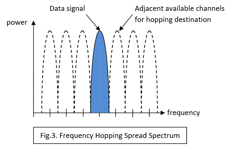
Frequency hopping is perhaps the easiest to understand. Invented to improve security for military communications, it involves the transmitter switching the carrier frequency between channels in a seemingly random manner. The legitimate receiver will know the sequence and be able to switch its local oscillator in step. (Fig.3).
This is great for one-to-one or one-to-many secure communication, but in our many-to one or many-to-many domestic situation a fixed hopping sequence cannot be used. Hardware is usually incorporated in RF modules to enable Carrier Sense Multiple Access (CSMA) operation making FHSS possible. There are two flavours of CSMA: Collision Detect, where the transmitter abandons transmission when it realises another device is using the same channel and Collision Avoidance, where it checks to see if the ‘coast is clear’ before using a particular channel. As more and more devices try to access the limited number of channels within the band, performance degrades relatively gracefully until eventually, practical communication ceases. FHSS was designed to resist deliberate jamming by a narrowband interference signal simply by jumping away to another channel. In civilian applications it can handle accidental interference from other transmitters in the same way. Even if another device permanently blots out one or two channels, operations can continue.
DSSS
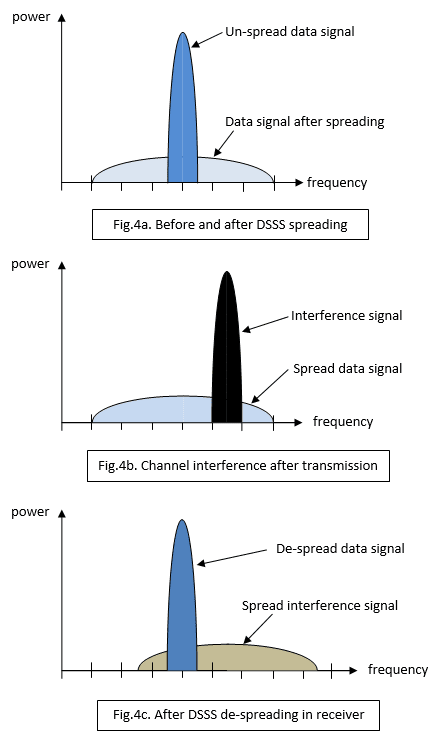
With DSSS, the NRZ data signal is modified using a random-code sequence (Fig.2c) rather like data whitening, except that the sequence is fixed (in this example an 11-bit code) and the register holding it is clocked at 11 times the data clock rate. This means that each logic 0 bit in the data is replaced by an 11 ‘chip’ sequence and a logic 1 by the inverse of the sequence. The bandwidth of the signal has as a result been increased by a Spreading Factor (SF) of 11 and, importantly, the power per Hz (Power Spectral Density) reduced by the same amount (Fig.4a). A whole lot of redundancy has been added with a single bit represented by a string of eleven ‘chips’. This modified baseband signal is then used to modulate an RF carrier in frequency or phase. The receiver demodulates the signal and then presents it to a correlator circuit which turns the chip sequences back into the original data signal. The correlator works by comparing a copy of the 11-bit chip code with the incoming chipped signal. When an exact match is found, its output briefly goes to a high positive value before returning to zero with the next chip clock pulse. On the other hand, a match with the inverse code generates a high negative pulse. It’s not difficult to reconstruct the NRZ logic signal from this sequence of bipolar pulses,
You might imagine that other 11-bit sequences within the chipped data would generate at least some output from the correlator. In fact, they don’t. If some noise flips one or two chip values all that happens is that the size of the match output is reduced. The reason lies with that 11-bit chip code. It’s a very special code called a Barker code and there are very few of them. Now you can see the effect of redundancy – loss of a few chips will not lead to loss of the whole data bit.
Effect of Interference and Noise on a DSSS System
Fig.4b shows a burst of narrowband interference (or jamming) from a nearby non-DSSS signal. Fig.4c shows the spectrum of the data signal and interference after dispreading by the correlator. The data signal spectrum is back where it was, but the interference has been spread. The difference in the data power spectral density before and after despreading is called Processor Gain. Obviously if a large number of simultaneous interference signals intrude into the bandwidth occupied by the spread signal then there may be trouble. There may even be what’s called a Coexistence problem where different communications systems operate in close proximity. Here is an example.
The Coexistence problem: Wi-Fi versus Bluetooth
A coexistence problem surfaced some time ago between Bluetooth which uses FHSS and Wi-Fi working with DSSS. Both systems operate in the same 2.4GHz ISM frequency band, so contention is inevitable. Both have very short range and one way of dealing with the problem is physical separation. Bluetooth class 3 devices have a maximum range of about 1m, with the commonly used class 2 coming in at 5 to 10m. Of course there is nothing to stop you using a class 3 transmitter (low RF power output) with a class 2 receiver (higher sensitivity). Bluetooth also uses Adaptive Frequency Hopping which avoids heavily used areas of the band. A third mechanism for coexistence is being used in the latest generation of transceiver devices. These contain the hardware for both Bluetooth and Wi-Fi communication with a co-ordinator circuit which prevents both transmitting at the same time. A more recent clash has been found between Bluetooth and 4G mobile phone signals when the two systems are co-located in a smartphone. This has led to the issue of Bluetooth version 4.1 which allows coordination with the 4G transmitter as described above.
CSS
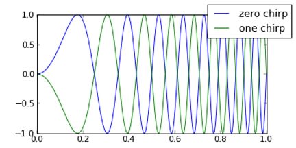
The latest spread spectrum technique is also one of the oldest, being used originally to improve radar performance. Each coded bit consists of a sine-wave linearly rising in frequency across the NRZ bit interval – a ‘chirp’. (Fig.5). Notice that logic 1 and logic 0 are both represented by a rising frequency signal, but have opposite phase to each other; rather like the code sequence and its inverse with DSSS, but with a massive increase in the equivalent chip/bit rate. The frequency range of the chirp defines the bandwidth of the coded baseband signal, so roughly:
For DSSS, Rc = Rb x SF where Rc = Chip rate Rb = Bit rate SF = Spreading Factor
But for CSS, Rc = Rb x 2SF that’s 2 to the power SF!
Straight away you can see two things: An enormous amount of redundancy has been applied and for a given bandwidth channel the data rate is much smaller than for DSSS. For SF = 10 for example, the chip/bit rate for CSS would be 1024. In theory you could get similar performance from a DSSS system using 1024-bit chip codes. There is a problem though: there are no Barker codes that long. In fact the longest known is just 13 bits. Of course the other design headache concerns the big increase in complexity of the correlator. That’s what has limited chirp technology to military radar systems until the arrival of supercomputer processing power on cheap tiny (micro)chips.
Fig.5 Chirp Spread Spectrum: Chirp for logic 1 (Green), logic 0 (Blue)
CSS and the Internet of Things
Chirp technology in chip form (I wish they’d coined another term instead of ‘chip’ for CSS.) has arrived just in time for the IoT:
- It offers much more reliable signalling over long range without exceeding the maximum RF output power allowed for the licence-free ISM frequency bands - usually the sub-1GHz ones such as 868MHz.
- The very low data rate is not a problem as most IoT nodes will involve battery-powered units that only transmit short bursts of sensor data occasionally and spend the rest of the time ‘asleep’.
- CSS can operate in a phenomenonly noisy environment and still recover a signal that is completely buried in noise. In other words, operation with a negative Signal-to-Noise Ratio is possible.
- The performance of a CSS channel can be enhanced using good old-fashioned Forward Error Correction too.
LoRa™ – an implementation of Chirp communication technology
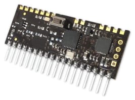
Chip maker Semtech now supply CSS-based radio devices using their own communication protocol called LoRa and modules featuring these devices from RF Solutions are available now from RS Components. Development is made even easier by using the Arduino™ shield.
In Part 4: Search ‘internetofthings’ on the RS Components website and you’ll get over 400 products: chips, modules and development kits in various categories; Radios, Modems, Telemetry, Remote control… with various protocols such as IEEE 802.15.4, ZigBee, 6LoWPAN…. I’ll have a go at matching the hardware/software to some applications.
If you're stuck for something to do, follow my posts on Twitter. I link to interesting articles on new electronics and related technologies, retweeting posts I spot about robots, space exploration and other issues.


Comments