RF Communication and the Internet of Things, Part 2
Follow articleHow do you feel about this article? Help us to provide better content for you.
Thank you! Your feedback has been received.
There was a problem submitting your feedback, please try again later.
What do you think of this article?
In Part 1 of this basic introduction to designing wireless communication links, I presented a fundamental calculation, that of the Link Budget which determines how much RF transmitter power is needed or how sensitive the receiver needs to be, in order to communicate over a specific distance in Free Space. Now the question is, what sort of data-rate can we expect? The answer depends on what proportion of the signal reaching the demodulation circuits of the receiver is just random electrical noise: noise added in the channel between the transmitter and the receiver antenna, plus noise added by the receiver input amplifier itself.
What is Noise?
Noise is an unwanted random signal that gets added to your wanted random signal. It can’t be filtered out because it contains all the same frequencies as the information signal. Its randomness is no help either: the information signal is also random and unpredictable. It wouldn’t be information if it was known in advance now would it? It’s called White noise because it contains all frequencies with a flat spectrum – the hiss between stations on an AM radio, the ‘snow’ on an un-tuned analogue TV. For the purposes of calculating noise performance in communication channels there is a mathematical model and it’s called Additive White Gaussian Noise or AWGN. It should be noted that there is a difference between Noise and Interference. Noise is generally random, while interference tends to come from other man-made sources like another radio station operating in the same frequency band.
Sources of Noise
Just about everything with a temperature above Absolute Zero (0 K) generates noise: there’s naturally occurring noise, noise generated within the receiver circuits and man-made noise from poorly-screened electrical systems. Most of it is classified as Thermal Noise of the AWGN variety and its intensity is proportional to Absolute temperature T (in Kelvin) and the measurement bandwidth B (in Hz).
Noise Power = kTB watts where k = Boltzmann’s Constant , 1.38 x 10⁻²³ W/HzK
The ratio of noise power to the signal power (the Signal to Noise ratio or SNR) at the receiver demodulation stage will determine the maximum data rate in bits per second that can be reliably sent across the comms channel.
SNR = S/N where S = Total Signal Power and N = Total Received Noise Power, both in watts
Data from Pluto
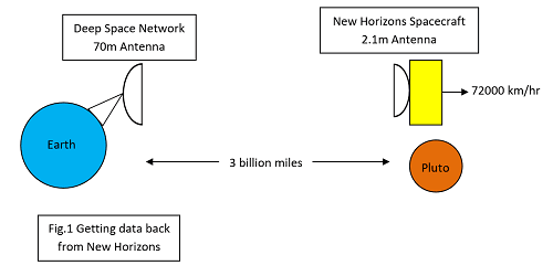
Let’s go back to the New Horizons space probe example (Fig 1) introduced in Part 1 and crunch some numbers to get an idea of what sort of data rate we can expect over a channel 3 billion miles long. The Downlink to Earth is always going to be the weakest part because of the limited transmitter power and relatively small antenna of the spacecraft. First though, let’s calculate the link budget for the Uplink based on a 70m parabolic dish belonging to NASA’s Deep Space Network. This antenna can radiate 400kW of X-band energy into space. Yes, that’s 400,000 watts (56dBW) or the output of over 400 microwave ovens. Needless to say, the transmitter is only activated when the sky is clear of objects that might get fried and the dish must be pointing well above the horizon! And that’s before we factor in the antenna gain calculated from:
G = 10log10k(πD/λ)2 dB where k = dish efficiency, D = dish diameter, λ = wavelength
For our 70m antenna, 70% efficient, transmitting at 7.2GHz we get G = 72dB. It’s 70% efficient because some signal ’leaks’ around the edge of the dish and some is even emitted from the back. The same formula gives us the Gain of the spacecraft 2.1m High-Gain Antenna as 44dB. The Free Space Loss over 3 billion miles using the formula from Part 1 comes out at about 303dB. So the link budget calculation gives us the signal power arriving at the spacecraft receiver:
Probe Rx power = 56 + 72 + 44 - 303 = -131dBW
Providing the receiver doesn’t add a lot of noise it should have enough sensitivity to demodulate the signal with a reasonable error rate that can be handled with error correcting coding.
Now for the downlink. In this case the transmitter power is a mere 12W (or 10.7dBW) and the antenna gain is only about 44dB, so the DSN dish on Earth only gets:
DSN Rx power = 10.7 + 72 + 44 - 305 = - 178dBW
But is it enough and what sort of data rate can we expect? We need to look at the noise to find out.
Receiver Noise Performance
In order to see what sort of data rate this channel can give us, we will find the receiver signal to noise ratio (S/N) but in a ‘normalized’ form independent of channel bandwidth and bit-rate.
Now S/N = (EB/NO) x (R/B) where EB = Signal Energy per Bit, NO = Noise Power per Hz and R = Bit Rate, B = Noise Bandwidth
Clearly we don’t know R or B yet but we can find EB/NO. We also have the value for S calculated above (-178dBW).
So S/NO = (EB/NO) x R as N = NO x B which means we need a value for NO. That comes from the Noise Power equation above, modified to: NO = kT W/Hz. What value do we use for the Noise Temperature T? Not having access to the receiver specification means a certain amount of guesswork here. The ‘Sky Noise’ temperature is likely to be pretty low, around 9K, because the antenna sensitivity is confined to a narrow upward beam. The antenna and cable add about another 1K. Now a receiver, operating at room temperature might add another 293K but the DSN front-end RF circuits are cryogenically cooled down to around 20K giving us a total noise temperature of around 30K.
So NO = 1.38 x 10-23 x 30 W/Hz = -213.8dBW/Hz
Now we can find S/NO = -178 - (-213.8) = 35dB/Hz (Remember division is subtraction in dBs!)
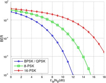
To get to the data rate R we still need to find a value for EB/NO and to do that some design decisions will be required: what Bit Error Rate can be tolerated and which modulation scheme will be used. The graph in Fig 2 allows you to read off the value of EB/NO for a given BER using four sorts of Phase-Shift Keying (PSK) modulation scheme.
PSK is frequently used in space communication but similar curves are available for the Frequency-Shift Keying (FSK) used in many ISM band Internet of Things systems. An error rate of 1 in 1000 bits (BER = 10-3) should be acceptable. Reading off the curve for BPSK/QPSK we get an EB/NO of about 7dB. Nearly there! Going back to our equation S/NO = (EB/NO) x R and plugging the values obtained gives us:
35 = 7 x R but remember the numbers are in dBs so this becomes:
R = 35 – 7 = 28dB --> 631bps
Fig 2. BER Curves (Wikipedia: Splash)
At last, we have a figure for the rate in bits/sec we can expect from New Horizons at Pluto and you can see why it’s going to take about 18 months to send all the data! It’s pretty rough and some other factors have been ignored, but it’s not far off. Of course even this figure is falling as the spacecraft moves away at 72000km/hour. That movement itself introduces a complication in the form of a Doppler Shift in the frequencies reaching the receiver, which means that the demodulation circuits have to account for that as well. The upside of this frequency shift is that it does provide mission control with a figure for the spacecraft’s speed. New Horizons does have a trick up its sleeve: there are two 12W power amplifiers on board to provide failure redundancy. They both feed the antenna at the same time but with opposite signs of circular polarisation. Reception of both signals by the DSN gives up to 2dB improvement in the SNR.
Meanwhile, Back on Planet Earth with the Internet of Things
How much of the above is applicable to the ‘easier’ challenges of the IoT engineer?
- With the short distances involved nothing like those levels of transmitter power are needed. The antenna gain will also be very low because of the need for it to have as close as possible an isotropic or omnidirectional radiation pattern. The familiar stubby monopole antenna has a gain of about 5dB. There is unlikely to be a need for the massive gain, but focussed ‘beam’ of the parabolic dish.
- The ‘Sky’ noise reaching the receiver will be much higher because of all the sources of noise near the ground in the region of maximum sensitivity for the antenna. In a quiet area the Noise Temperature will be around 290K but in a busy commercial area it can be over 1000K. As a result the receiver’s own noise temperature is less significant and there will be no useful advantage in immersing your IoT project in liquid nitrogen!
- An entirely predictable problem with IoT applications now becoming apparent is overcrowding in the limited ISM license-free radio frequency bands. As the home fills up with IoT sensors, all operating, for example, in the 2.4GHz band shared by existing WiFi and cordless landline telephones, clash-rates will rise to the point where information transfer ceases. Although protocols such as Bluetooth do use techniques to reduce the effects of this ‘Interference’, much more development is needed to prevent the inevitable gridlock.
- As I suggested in Part 1, much of this calculation has already been done for you by the manufacturers of low-power ISM-band wireless modules. Search for 'ismband' on the RS Components web site to see some of them. If the default settings for a device deliver the performance you need, job done. But most modules are programmable if you need something different.
In Part 3, I’ll take a look at how IoT wireless transmissions are crammed onto the crowded airwaves using Spread-Spectrum techniques such as Frequency-Hopping (FHSS), Direct-Sequence (DSSS) and the new kid on the block (for this application at least), Chirp (CSS).
If you're stuck for something to do, follow my posts on Twitter. I link to interesting new electronics components and development kits (some of them available from my employer!) and retweet posts I spot about robot, space exploration and other issues.


