Renesas Inductive Position Sensor – IPS2550
Follow article
 Dave from DesignSpark
How do you feel about this article? Help us to provide better content for you.
Dave from DesignSpark
Thank you! Your feedback has been received.
Dave from DesignSpark
There was a problem submitting your feedback, please try again later.
Dave from DesignSpark
What do you think of this article?
By Mike Donnelly - Principal Engineer at Siemens Digital Industries Software.
The IPS2550 is a magnet-free, inductive position sensor IC that can be used for high-speed absolute position sensing in automotive, industrial, medical, and consumer applications. The IPS2550 uses the physical principle of eddy currents to detect the position of a simple metallic target that is moving above a set of coils, consisting of one transmitter coil and two receiver coils.
Product Specifications:
| VEL | 600,000 RPM Max. |
|---|---|
| Accuracy (3.3V) | +/- 0.2 %FS |
| Accuracy (5.0V) | +/- 0.1 %FS |
| Temperature Limits | -40C to 160C |
See the IPS2550 Datasheet for more detailed product information. Motion Sensor ICs like the IPS2550 are available to buy from RS.
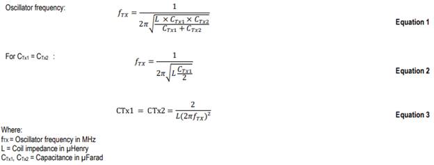
The oscillator frequency is determined by the values of Tx coil L and capacitors CTx1 and CTx2 as the following:
The Angle Tracking System shown below is a “Live – Tunable” design. You can change any of the system parameters that are shown in blue, to match the specific requirements of your application. Then just run a new simulation (by clicking on the green “play” arrow) to see the results of those changes.
This application example demonstrates the IPS2550 ability to track a target shaft rotation as it completes one full mechanical rotation, from 0 to 2*Pi (6.28 radians) in 0.2 msec. This is equivalent to 300,000 RPM. Many design parameters can be changed by the user, to see how they affect this systems ability to track that angular rotation. This includes the Inductive Position Sensor’s (IPS) target “shape” (i.e., electrical cycles per mechanical revolution), the sensor inductance and the external capacitance values that set the oscillation frequency, the input supply voltage (Vdd), and even the analog low-pass filter capacitance, number of quantization bits and the sample rate for the angle detection algorithm.
Try it yourself!
If you change the IPS parameter “n” (target electrical cycles per shaft revolution) from 1 to 2 and re-run the simulation, you’ll see how the system performs at the effective maximum “electrical” rotation rate of 600,000 RPM. You can also change the low-pass filter capacitors over a wide range of values, to see the effect on both the desired reduction of demodulation product noise, but also on the undesired delay or phase shift of the sensed rotation angle.
Feel free to try other system configurations. Note that you can also move waveform (scope) probes around to see other signals on nets or internal to any of the components on the schematic.
-
Do you have questions on the above? Ask in the comments section below and Mike is here to help!