Refurbishing a Classic Quad 303 Amplifier
Follow article
 Dave from DesignSpark
How do you feel about this article? Help us to provide better content for you.
Dave from DesignSpark
Thank you! Your feedback has been received.
Dave from DesignSpark
There was a problem submitting your feedback, please try again later.
Dave from DesignSpark
What do you think of this article?
Iconic 1960s British transistor amplifier gets an overhaul.
It really says something when a HiFi amplifier that was first introduced coming up for sixty years ago still has a strong following and many units remain in circulation. Such is the reputation of Quad, who were once regarded as the pinnacle of British HiFi manufacturing and over the years have been bestowed with numerous accolades, including the Queen's Award for Technological Achievement and Design Council awards, amongst others.
Around 94,000 Quad 303 amplifiers were manufactured over a period spanning 1967 through to 1985. Their first transistor amplifier for the domestic market — Quad held off moving to solid state amplification until they could exceed the performance and reliability of their existing valve designs — the 303 proved a hit with HiFi enthusiasts and professional users such as the BBC alike. No doubt due to a combination of the amplifier’s excellent sound, compact nature, unique industrial design and notably robust construction.
However, with the last units coming off the production line 39 years ago, some amplifiers passing through many hands and the variable quality of the work carried out on them, it is always a good idea to give such vintage electronics a thorough checking over. In this article, we take a look at replacing capacitors (a.k.a. “re-capping”) and setting up the amplifier according to the service manual. Following which the amplifier should be good for a few decades more!
Specifications
The Quad 303 is a stereo power amplifier with the following specifications:
- 45W per channel into 8 ohms load
- Distortion: 0.03% @ 70Hz, 0.03% @ 700Hz, 0.1% at 10kHz
- Frequency response: -1dB (ref: 1kHz) at 30Hz and 35kHz
- Output source impedance: 0.3 ohms in series with 2,000uF and 6uH
- Input level: 0.5Vrms
- Input impedance: 22K in parallel with 60pF
- Inter-channel crosstalk: 30-10,000Hz better than 60dB
Although these may not seem like impressive figures now, the 303 provided excellent performance for the time and still sounds great today. Of course, a class D amplifier could deliver 2 x 45W in far less space and at a tiny fraction of the >8kg weight, but it wouldn’t be a classic pure analogue design and, after all, vintage cars are not bought for reasons of convenience and efficiency.
In terms of its physical design, the 303 at first glance appears almost identical to the Quad 50 mono amplifier, which we previously serviced a pair of back in 2022. However, a somewhat unusual transistor amplifier, the Quad 50 employs an audio output transformer — much like a valve amplifier — and this has a number of taps on its secondary, which allows it to be configured for different output impedances. Whereas the 303 has no output transformer, is not simply two Quad 50 amplifiers in one chassis and is rather instead of a markedly different design.

The Quad 303 was typically paired with a 33 Control Unit (preamplifier). Though in professional settings such as BBC studios it would have usually been connected to a mixing desk output.
More often than not, all that is required to bring a vintage Quad amplifier up to spec is to replace old, dried-out electrolytic capacitors and go through the setup procedure. Of course, sometimes there may be other issues, such as blown transistors, but this is rare.
Re-capping

An electrolytic capacitor crushed by its mounting clip.
Upon removing the covers it became immediately apparent that this amplifier had been worked on previously and the original electrolytic capacitors replaced. On closer inspection, it transpired that the physically large capacitors which are secured to the chassis had suffered serious damage.
Although smaller capacitors fitted to driver boards may have been fine, it was decided to replace these also, given the questionable nature of previous work and the small additional cost to replace them.
Bill of materials
The following parts were ordered to complete the work:
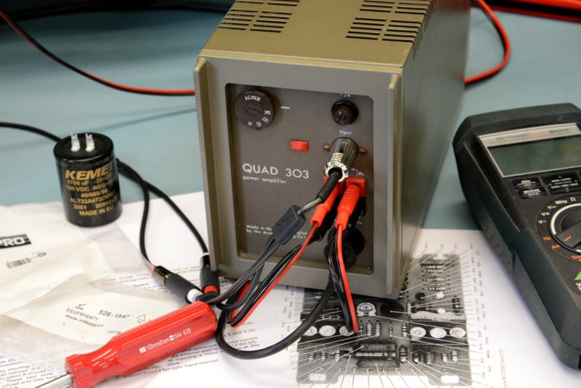
- 4x KEMET 4700μF Aluminium Electrolytic Capacitor 100Vdc, Solder Lug (339-7981)
- 2x Panasonic 470μF Aluminium Electrolytic Capacitor 25Vdc, Radial (526-1547)
- 2x Panasonic 10μF Aluminium Electrolytic Capacitor 63Vdc, Radial (747-2180)
- 2x Panasonic 47μF Aluminium Electrolytic Capacitor 63Vdc, Radial (747-2200)
- 2x EPCOS 680nF Polypropylene Film Capacitor, 160Vac, 450Vdc (882-9297)
Running through this list we first have the aforementioned capacitors which are secured to the chassis. Two of which are connected in parallel and provide power supply smoothing, while the other two are used one each in the amplifier channel outputs. These would all have originally been 2,000uF / 100V / 1.5” (38mm) diameter and had been replaced with 12,000 uF / 120V / 40mm diameter parts. Their clips then being overtightened and resulting in the capacitors being severely damaged, to the point of piercing the cans and electrolyte being lost.
With improvements in technology over the years capacitors have become smaller. Which is generally a good thing, although it can present physical and/or aesthetic challenges when maintaining vintage electronics. One solution is to go for a higher capacity and/or voltage rating so that the replacement is a better mechanical fit and looks right. However, while increasing the value of power supply smoothing capacitors can be seen as a good thing, it can also put increased strain on upstream components, such as a bridge rectifier, due to the increased inrush current at power on.

With the above in mind, it was decided to replace the 12,000uF capacitors (which were originally specified at 2,000uF) with 4,700uF parts. These are much shorter than both the original parts and those fitted more recently, but cannot be seen when the covers are fitted.
Next, we moved on to the smaller capacitors fitted to each of the two driver boards.
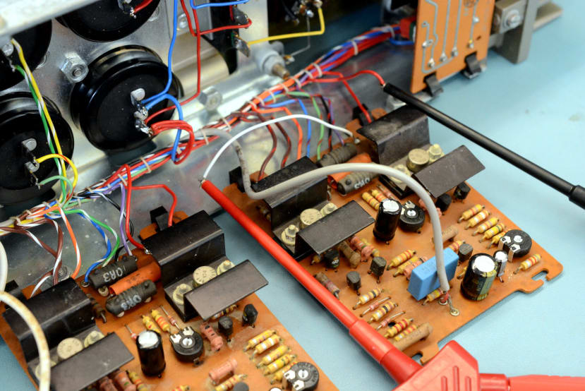
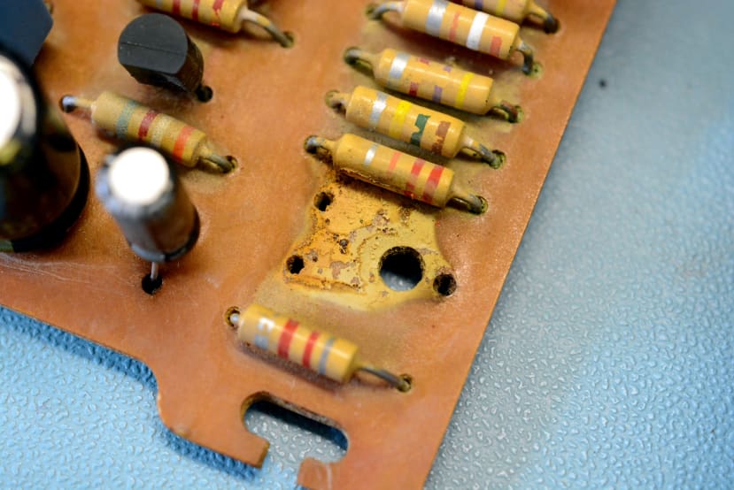
Quad 303 driver board.
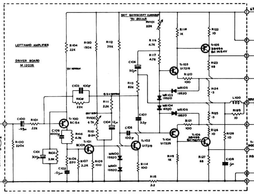
Capacitor C101 was originally specified at 300uF and a more common 470uF part was selected for this. C104 was specified at 12uF and a 10uF part was selected to fit to each driver board. Again a more common value of 47uF was selected to replace the 50uF specified for C106. In each case, the voltage rating of the replacement part is higher than that originally specified by Quad.
C100 is the driver input capacitor and a tantalum type would have originally been fitted. This had been replaced at some point by an electrolytic. However, it’s generally accepted that polypropylene film-type capacitors will provide better performance in an audio signal path, hence 680nF parts were ordered to replace the electrolytic capacitors fitted in this position in each drive board.

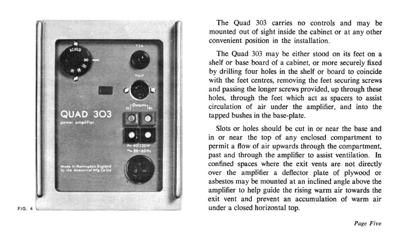
Copies of the Quad 303 service manual can be found online and this provides a bill of materials, details of component positions, setup instructions and notes on fault finding.
Fitting

The new 4,700uF capacitors were fitted into the original clips and as they are of a slightly larger diameter, the old imperial 4BA screws were replaced with longer 16mm M4 screws and M4 nuts.
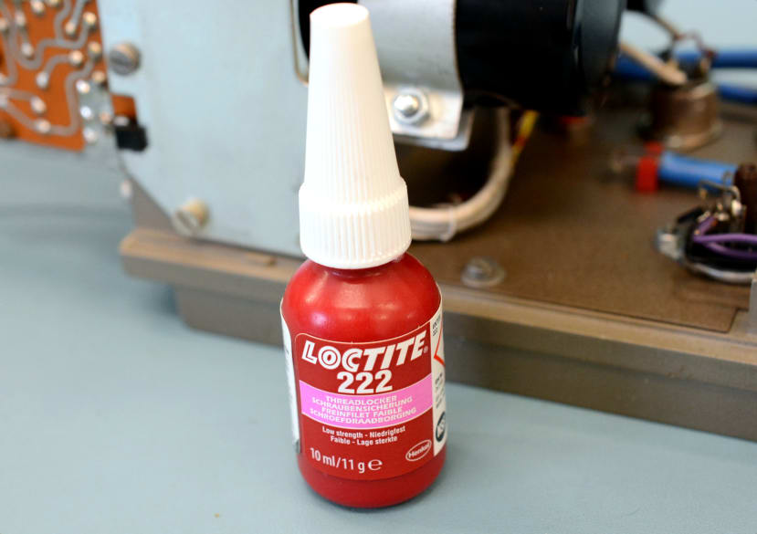
The clips were gently tightened to avoid crushing the capacitor cans, with Loctite 222 threadlock (514-509) applied to help prevent the screws from working loose.

The new capacitors fitted into the holes in the chassis without a problem, however clip mounting holes didn’t fully line up due to the larger diameter of the capacitors pushing these out slightly. Hence the holes were widened out a little with a needle file — a sub-optimal but pragmatic fix. Threadlock was again applied to the screws when securing the capacitor clips to the chassis.

Wires were then soldered in place on the underside of the chassis.
Now on to the two-channel driver boards.

Above can be seen a much larger polypropylene film capacitor next to the electrolytic it replaced on a driver board input.
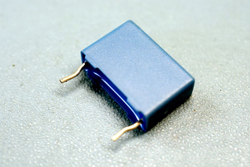
In order to get this to fit in position the legs had to be bent slightly.

Above can be seen one of the driver boards, with three new electrolytic and a polypropylene film capacitor fitted.
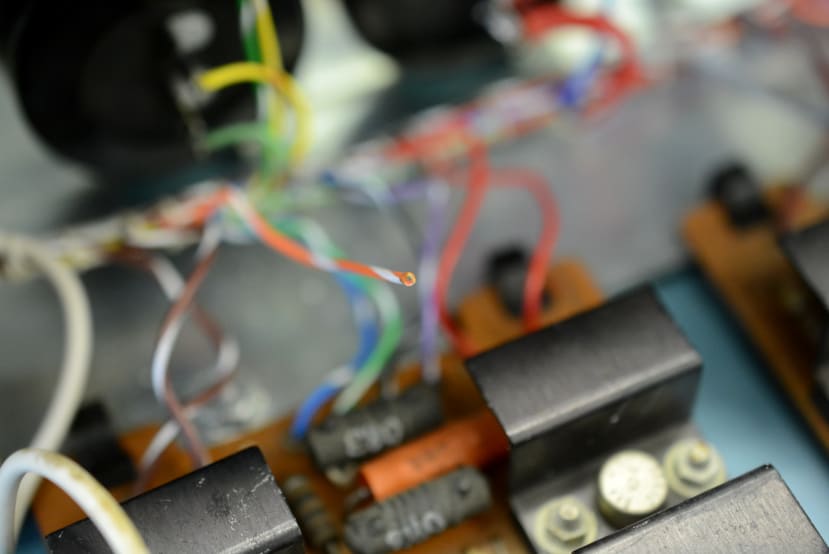
Classic Quad equipment is typically a pleasure to work on since it is designed for ease of servicing. With the 303 boards can be unclipped at one end and hinge on the chassis, providing convenient access to each side. However, one slight issue encountered with this particular amplifier is that every so often a wire would break off, as a result of boards being moved to and fro and presumably said wires had previously been flexed numerous times when serviced in the past.
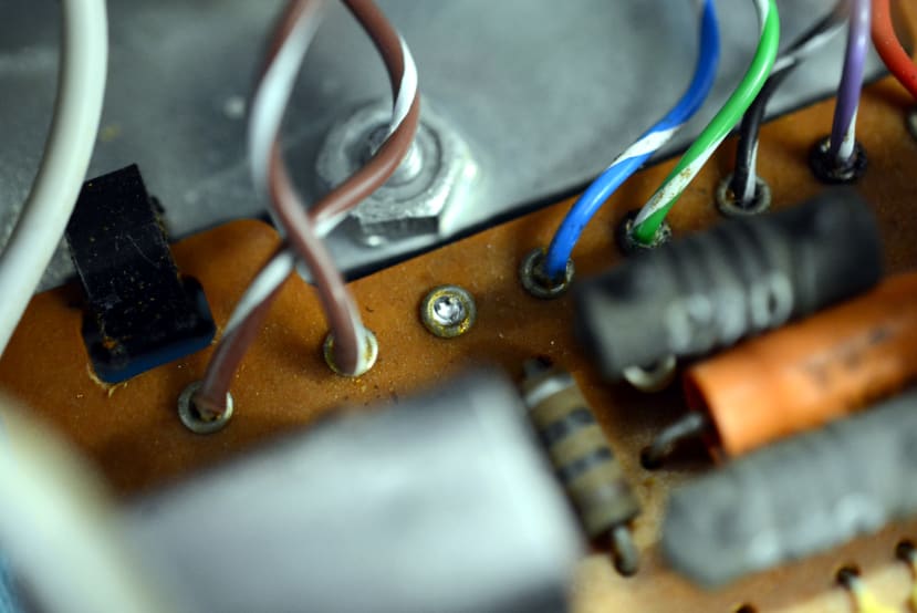
This simply meant that wires had to be re-soldered, with extra care taken to avoid unnecessarily flexing them and double-checking to make sure that no more were about to break free.
Setup
The service manual provides setup details and the procedure is comprised first of a step which is carried out on the power supply regulator board:
- Adjust RV200 for 67 volts as measured between tags 1 and 9 on one of the driver boards.
Plus two steps which are carried out on each of the two-channel driver boards:
- Adjust RV100 for 33.5 volts between tags 5 and 9;
- Adjust RV101 for 5 to 10mA quiescent collector current measured by breaking the external lead to tag 2 and inserting a meter in series.
The very first step involving the regulator board was completed without issue. Then the first of the above two steps was completed without issue on one of the driver boards, but with the other driver board it was not possible to set the voltage to much above 20 volts.
Upon closer inspection, it appeared as though electrolyte from the old damaged capacitors which were fitted in the chassis above, had run down on to this board. Suspecting damage to RV100, it was removed and an orange stain was found under it.

The removed trimmer potentiometer looked in a pretty sorry state.

The board was cleaned with isopropyl alcohol and the trimmer potentiometer replaced. Following which RV100 could be set for the target 33.5 volts measurement.
The second setup step on each driver board proved a touch fiddly and suspecting slightly noisy trimmer pots, RV101 on each board was replaced. Then just for good measure — and visual symmetry! — RV100 was also changed on the other driver board to a matching new part.
Thereby completing the repairs and setup.
Final words
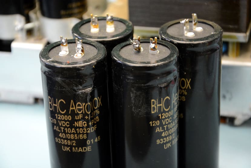
Badly damaged electrolytic capacitors which were replaced.
There is something particularly special about classic Quad audio equipment, a combination of its industrial design aesthetic, with utilitarian touches, and a solid, notably orderly construction. Plus of course the sound and ease of servicing. Hopefully this amplifier will now live on for at least another twenty years, if not more.
Comments