Tighter Fuel Metering with a “Quick-Off” Injector Driver
Follow article
 Dave from DesignSpark
How do you feel about this article? Help us to provide better content for you.
Dave from DesignSpark
Thank you! Your feedback has been received.
Dave from DesignSpark
There was a problem submitting your feedback, please try again later.
Dave from DesignSpark
What do you think of this article?
By Mike Donnelly - Principal Engineer at Siemens Digital Industries Software.
Although the automotive industry is moving rapidly toward electrification, there is no reason to stop improving the performance and efficiency of traditional gasoline engines. New power electronics technology from Nexperia can help with that too!
Accurate fuel metering is important for robust engine control, and that translates into tight timing requirements for the fuel injector opening and closing. One method to improve the response of the injector closing is to provide a large back-voltage at the end of the injection event, to rapidly reduce the injector solenoid current. This back voltage can come from the “avalanche” of the main injector driver switch. That switch must be rated to handle repeated avalanche conditions, like the BUK9K13-60RA (240-1816) Power MOSFET from Nexperia. This fuel injector driver example shows the benefit of using that part for better timing control of fuel injector cut-off.
The driver uses two of those MOSFETs to control the injector current. In addition to the typical high side MOSFET (M1) and the freewheel diode (d1), an additional MOSFET (M2) is placed in series with the solenoid current path to ground.
During the injector "FIRE" sequence, the driver logic commands an initial "pull-in" current of 3A, using a current sense feedback and PWM control of the M1 switch to regulate the current level. After the initial pull-in period, that current level can be reduced to conserve energy. This is possible because less current is needed to "hold" the solenoid closed. During this entire "FIRE" time window, M2 remains ON, allowing the solenoid current to flow freely to ground and then back to the positive terminal of the solenoid through the diode. The low voltage drop around the loop helps sustain that current through the OFF phase of the PWM.
But at the end of the injection cycle, that current needs to be cut-off as quickly as possible, to provide a "crisp" injector turn-off or release of the solenoid. To achieve that, both M1 and M2 are turned OFF together, at time 26 msec. The remaining current in the solenoid inductance causes the drain voltage at M2 to build up until it avalanches. That is just under 68V for the BUK9K13-60RA, as seen in the magenta waveform which is zoomed in to focus on that turn-off event.
The solenoid armature position and current are shown by the yellow-orange and blue waveforms, respectively. Since this schematic is “Interactive”, and to help you see the effect of this "quick-off" feature, first plot those waveforms in the main viewer window (i.e. right-click on those waveforms and choose "Plot in Viewer"). Then change the logic state of "disable_quickoff" from '0' to '1' in the lower left of the schematic and re-run the simulation (click on the big green arrow!). Then plot the new armature position and current waveforms in the main viewer and drag these new waveforms onto the same graphs from the previous simulation. You'll see that the armature release at the end of the injection is delayed in the second case. The reason for that is the solenoid current's slow decay without the avalanche back-voltage putting the brakes on! The same results are captured in the image below. Click the image to see it in higher resolution.

Because the Nexperia MOSFET models used in this example include a detailed thermal representation of the internal junction-to-case heat transfer behaviour, as well as the temperature-dependent electrical behaviour of the device, we can monitor the junction temperature to make sure the part is not over-heated during any operating scenario. The M2 junction temperature is shown by the red waveform, with a rapid rise as it dissipates the solenoid’s stored energy during the avalanche event.
It might appear that this design uses an excessively large MOSFET for the application, a 40A-rated part for a 3A design seems like overkill! But from the BUK9K13-60RA Datasheet, you’ll see that another important rating is the maximum number of lifetime avalanche events. In the image below, I have taken the integral of the power dissipated by M2 during the avalanche event, and the result is approximately 8mJ of avalanche energy dissipated. Click the image to see it in higher resolution.

From Figure 5 of the datasheet (copied here for reference) you can see that the maximum number of lifetime avalanche events is approximately 3 billion at that energy level.
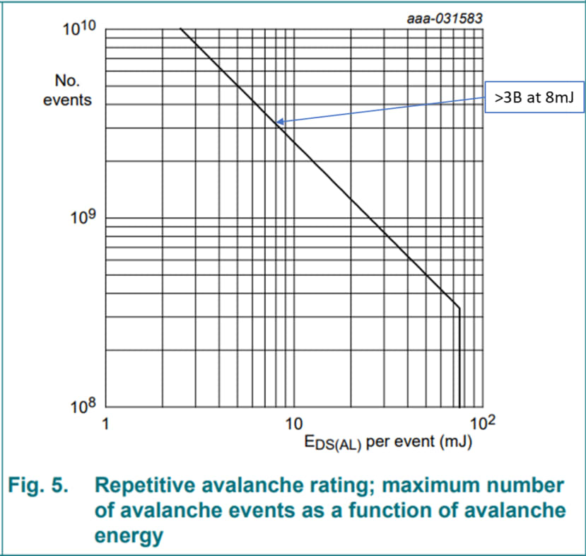
A smaller part, even if it has adequate current rating, may fall short on this maximum number of lifetime avalanche events. For a fuel injector which fires on every-other revolution of the engine, a minimum of 1.5 billion events per lifetime may be a practical design requirement for a private vehicle. (Assuming 3000 RPM, 3 hours of use per day, and 15 year life expectancy). It would be even higher for a commercial vehicle.
In a companion article, Mike explores how a simple open-loop voltage doubler circuit can improve the turn-on performance of the fuel injector!
-
Comments