PYTHON – Let the „Monty-language” enter Automation: Part 2
Follow article
 Dave from DesignSpark
How do you feel about this article? Help us to provide better content for you.
Dave from DesignSpark
Thank you! Your feedback has been received.
Dave from DesignSpark
There was a problem submitting your feedback, please try again later.
Dave from DesignSpark
What do you think of this article?
In part 1, I've shown the hardware setup. The “open” character of the RevPi project allows you to use tons of material ready to be downloaded from the internet. But the odd side of this versatility is, we need to install and set up all these third-party components, which is 90% of the project. In my example, I do use the fantastic library REVPIMODIO, written by my friend Sven Sager which will make IO access pretty simple as well as his PEVPIPYPLC for easy MQTT. So you will need some patience. But let’s do all this step by step...
First of all please do not forget to make a backup of your RevPi firmware before starting to change things. Then get the newest firmware upgrade and install it (see this article). Let me give you a quick insight into my way of working with “my baby” (I designed the RevPi product and developed the hardware).
I like using the device in “headless” mode: without HDMI monitor and keyboard, just 12 to 24 V DC connected, and an RJ45 network cable hooked to my LAN switch. The RevPi Core is in DHCP mode for factory default (it gets an unknown IP from the DHCP-server / switch). So I use the “advanced IP scanner” (free download here) on my PC to find the IP.
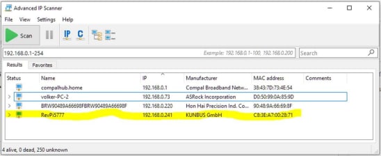
In my case, it got the IP 192.168.0.241 (please check the MAC or the name if you have more than one RevPi in your local network – MAC and number part of the name are both printed on the orange front plate).
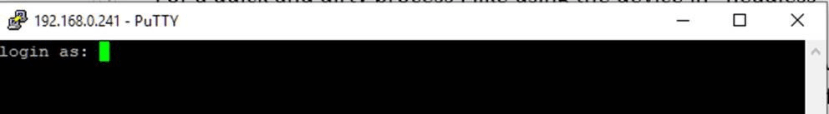
I then work with PuTTY (free download here) on my Windows PC to SSH the RevPi (connect to port 22). RevPi should come up with the Linux prompt for log in because SSH is enabled by default:
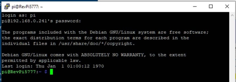
Use the shell Username printed on the label which sticks on the side of the RevPi’s case, which is “pi” per default (Linux is case sensitive!). The password is individual per default and derives from the internal serial number by using a hash algorithm. It is also printed on the label. Be aware that per default the keyboard layout of a RevPi is German. Any “z” or “y” needs to be swapped when using an English keyboard. Once you are logged in you will see the Linux prompt. On my RevPi it looks like this:
Both tools from Sven Sager, which I mentioned above, can be installed from the KUNBUS repository. This makes installation quite simple: Enter the shell command “sudo apt update” to make your package list actual and then enter “sudo apt install python3-revpimodio2”. Then install the other tool with “sudo apt-get install revpipyload”.
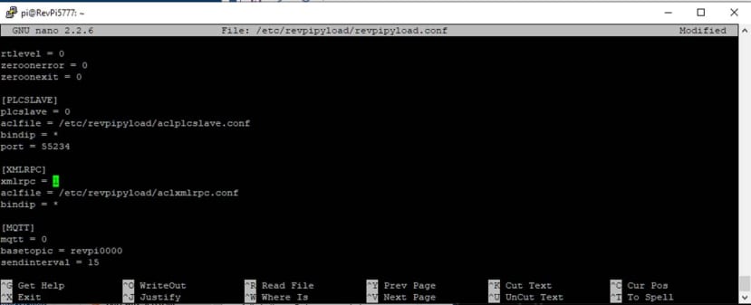
The revpipyload tool gives you remote control of your Python “PLC” over Ethernet. It uses XML-RPC (“Extensible Markup Language Remote Procedure Call“). Therefore we need to activate the XML-RPC server on our RevPi by editing the app’s configuration. Type in the shell command “sudo nano /etc/revpipyload/revpipyload.conf” and edit the section [XMLRPC], overwriting line “xmlrpc = 0” with “xmlrpc = 1”. For all the Linux dummies under you: This is a command line editor on your RevPi which is not yet in GUI mode. So your mouse is useless although you can use it on the windows GUI. You must use your arrow keys on your keyboard to navigate to the line you want to edit. Exit the command line editor with Ctrl-X and accept saving the changes to the given file.
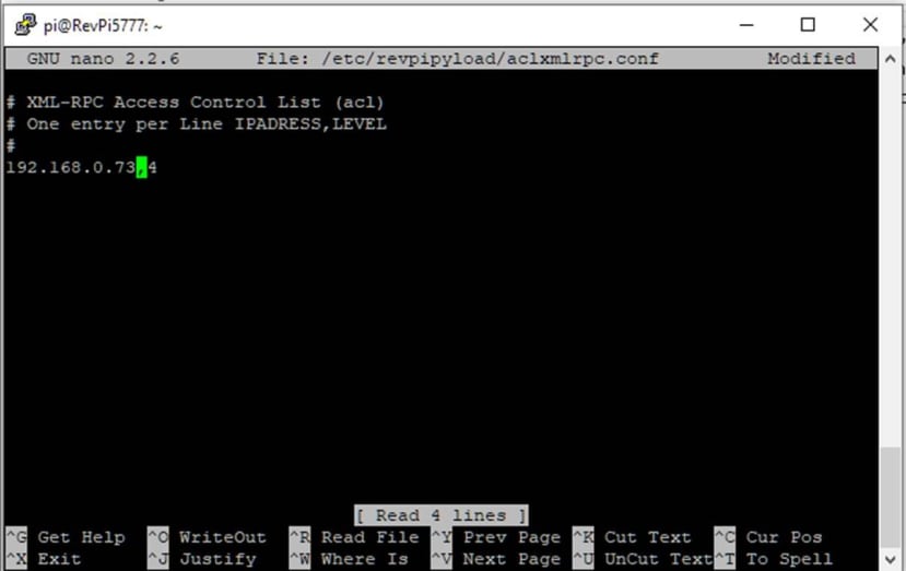
We should configure the permissions to access the XML-RPC server on our RevPi. We must add IP masks together with permission levels in the configuration file “/etc/revpipyload/aclxmlrpc.conf”). In my case, I add the IP of my Windows PC with permission level 4 (which is the highest level). So I type the shell command “sudo nano /etc/revpipyload/aclxmlrpc.conf”. and add the line seen in this screen dump:
As we will need the GUI of RevPi when writing and debugging our Python software, we need to either use an HDMI monitor, USB mouse and USB keyboard, or we use remote desktop access from our PC. As I said, I like to use RevPi in headless mode. Therefore I need to activate the pre-installed “VNC service” using the shell command “sudo raspi-config”.
As we will need the GUI of RevPi when writing and debugging our Python software, we need to either use an HDMI monitor, USB mouse and USB keyboard, or we use remote desktop access from our PC. As I said, I like to use RevPi in headless mode. Therefore I need to activate the pre-installed “VNC service” using the shell command “sudo raspi-config”.
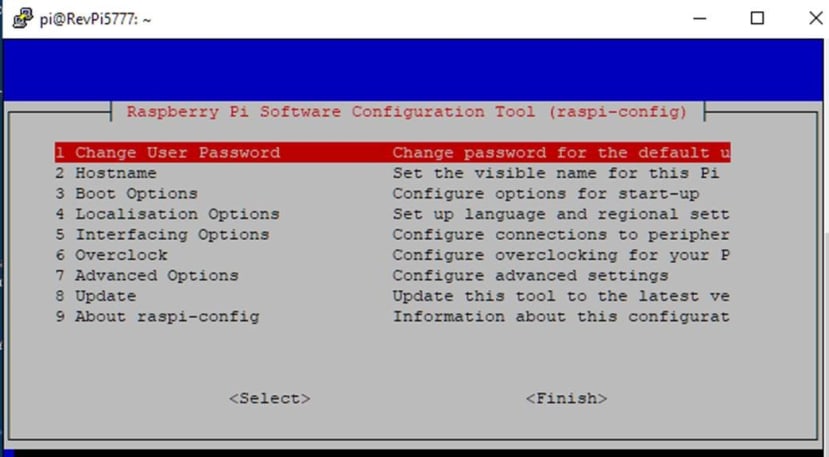
I move the cursor to number 5 “Interfacing Options”, press <enter> and get
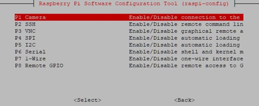
where I chose “P3 VNC” and press <enter>. On the next screen, I do activate VNC choosing “Yes”:
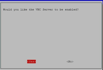
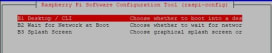
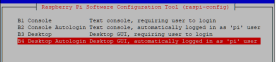
The system answers with “VNC Server is enabled”. When I have acknowledged this message with Ok, go on with “3 Boot Options” because I want the RevPi to boot into GUI mode. When I get the Boot submenu, I choose “B1 Desktop / CLI” and then “B4 Desktop Autologin”:
I need to select <Finish> to exit raspi-config. When the system asks for a reboot, I select “yes”.
When having the system rebooted, you will lose the SSH connection. So right click on the top of your PuTTY-Window after 30 seconds and choose “Restart Session”.
On the PC, I also need to install a VNC viewer (free download here). After having installed this application, I do start it and enter the RevPi’s IP as address and connect to it. Voilá, the RevPi desktop GUI magically opens as a window on my PC:

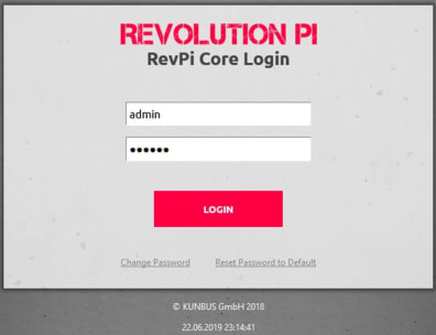
To configure the IO system (driver) of my RevPi, I can use the browser-based tool “PiCtory” by opening the RevPi’s IP on my Firefox. But first, the Web server of RevPi needs a login. Please note that this time the default user is NOT “pi” but “admin” instead. But the password is the same as long as you have not changed it.
Let me say a few words about security issues:
DO NOT USE THESE SETTINGS FOR A PRODUCTIVE SYSTEM!
Booting into GUI with no login at all is fine for the experimental system. A productive system needs to be protected by unique and strong passwords. It also needs to be either not connected to the internet, and any LAN which has a poor access policy or the internal Web server needs to be turned off. For now, we do need the Web server to run “PiCtory”.
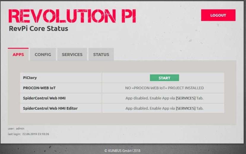
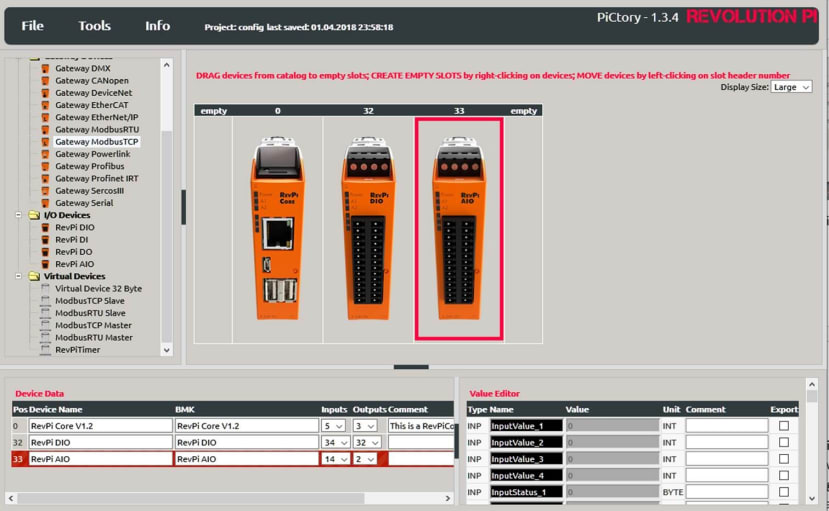
When I click on “START” in the PiCtory-line of the APPS-tabulator, I get to this configuration tool. Please consult the tutorials on the RevPi webpages to find out more about using PiCtory. I will only give a short instruction for my system, which is a RevPi Core, a DIO and an AOI module mounted on the DIN rail in exact this sequence. I drag and drop “RevPi Core V1.2” from the “Base Devices” list to the empty system slot “0”. Next, I drag and drop the “RevPi DIO” from “I/O Devices” to the empty slot right of the Core. And then I drag and drop the “RevPi AIO” to the empty slot right of the DIO module. This is what my window looks like and also what my DIN rail looks like:
There are some configuration values which need to be adjusted. I click on the AIO module to select it for the “value editor”. I scroll to the RTD1 section and change the values as shown:
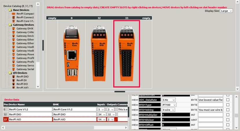
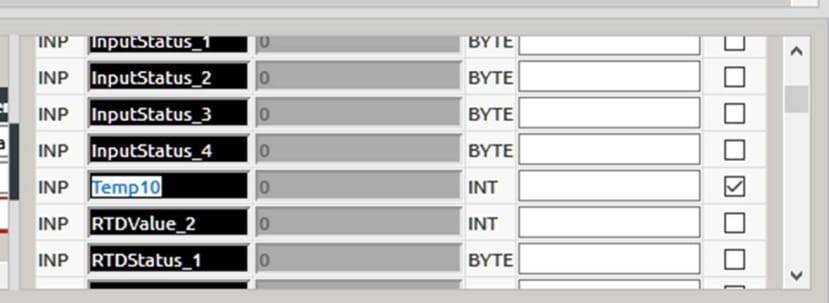
I use a 4-wire PT100 sensor, which is well calibrated, so I leave the scaling values (multiplier, divisor, offset) at their defaults to ignore scaling. The temperature values will be stored in the process image in °C * 10 (you get 254 for 25,4°C). Do not try to use the divisor value 10 to get direct °C values as this will result in losing the 1/10 °C values (the system uses 2-byte integers in the process image, so you get less precision). The address in the process image where the value is stored is called “RTDValue_1” which I change to “Temp10” (to indicate the multiplier 10 for °C). Do not forget to set the check mark for “export” because Sven Sager’s tool needs a checkmark for any value to be reported via MQTT.
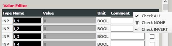
Now we proceed with the DIO module’s configuration. I click on the module to select it. With a right click on “Export” over the checkmark column in the value editor, I get a context menu where I click on “Check NONE” to deselect all values.
Then I use the value editor to rename output “PWM_1” into “PWM_heater1” as well as “PWM_2” into “PWM_heater2” and to modify the output type as shown in the screen dump:
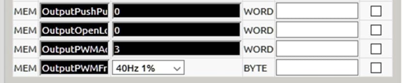
We do need output 1 and 2 to be a “Highside Switch” type (which is the default) and not “Push/Pull” type. The latter would use to FET switches: One to connect the output to GND for a value of 0 and one to connect it to the positive I/O supply voltage (usually 24 V) for the value 1. But we would get a current limit of just 100 mA per output in this mode whereas the Highside Switch mode can drive up to 500 mA from positive IO supply to GND when the output value is set to a 1. The outputs would only use a binary value of 0 or 1 per default. Only if you configure them to “PWN active”, they use the unsigned integer values “PWM_n”. To set any output to PWM active, we need to change the value of “OutputPWMActive”. This value is bit-coded. Each bit of this word stays for one output. Bit 0 stands for output 1, Bit 1 stands for output 2, and so on. The value of the configuration word is summed up by adding all bit values 2^n (n is the number of the output). In our case this is pretty easy: We need output 1 (bit 0) and output 2 (bit 1) to be PWM. As 2^0 + 2^1 = 1+2 = 3, we write a 3 into the configuration word. We leave the OutputPWMFrequency at its lowest value of 40 Hz because this results in the highest PWM resolution of 1%. So when you write 50 into the “PWM_heater” position of the process image, you get a 50% duty cycle on the output 1. For, eg. A value of 12 you would get 12% on time and 88% off time which results in 3 ms on and 22 ms off pulses.
I do need to save this configuration and load it to the system’s driver. So I click on “File” in the menu and then “Save as Start-Config.”. Then, I click on “Reset Driver” in the “Tools” menu which does load the configuration into the driver and activates it. This should turn all the LEDs on the three modules to green.
I have already downloaded and installed the Windows PC counterpart for the RevPiPyControl software, which is a Python tool called “RevPi PLC Control” (get it for free from here). This tool makes it easy to save and autostart Python scripts on the RevPi. But it also gives me a nice GUI based access to all current values of the process image. You can even set values via this GUI.
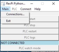
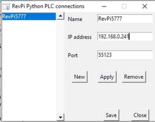
Use “Main” to get to “Connections…”. Enter a new connection by giving it a name and an IP. Leave “Port” at its default value of 55123. Click on “Apply” to get the new connection into the list on the left side. Then click on “Save” to save this connection. Finally, accept the message box which pops up by clicking on “Yes”.
If you click on “Connect” now, you get your new connection listed.
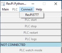
Chose it and your PC immediately connects to your RevPi. Ignore the red message “FILE NOT FOUND” which is only about not yet having a Python PLC program saved to the RevPi. But click on “PLC watch mode” to see your current module configuration (“Devices of RevPi”). If you click, e.g. on “RevPi AIO” you get listed all values from the process image:
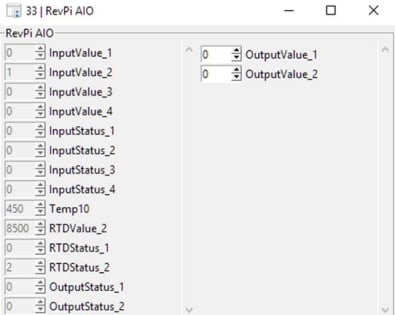
Temp10 shows me 402, which means I get grilled at 40.2 °C in my office (just kidding). When I click on “RevPi DIO” I get this list:
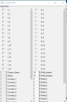
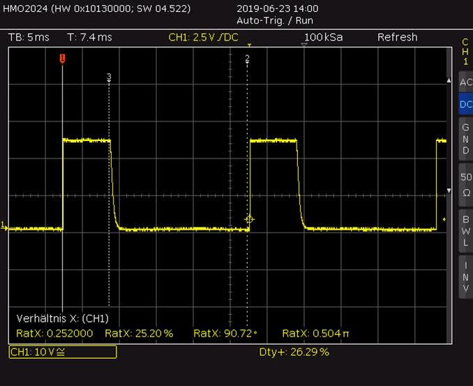
Entering 25 into “PWM_heater1” will not yet change the physical output. We need to click on “Autorefresh values” and then “Write values to RevPi” first. You get a warning message. If you know what you are doing, click on OK and enter 25 into PWM_heater to get a 25% duty cycle on the output 1. This is what you see on an oscilloscope:
That was lots of installation and configuration. So let’s have a short break before we go on with the Python program in part 3. Don’t miss it, subscribe!