PC interface for Arduino Uno - Part 1
Follow article Dave from DesignSpark
How do you feel about this article? Help us to provide better content for you.
Dave from DesignSpark
Thank you! Your feedback has been received.
Dave from DesignSpark
There was a problem submitting your feedback, please try again later.
Dave from DesignSpark
What do you think of this article?
Arduino Uno – PC interface part 1
- The project
- The Hardware
- The Software
- Arduino embedded software app
- PC app
- Conclusion
- Resources
The Project
This project shows how you can use the free version of Flowcode to create an embedded project that communicates with a PC via the serial port. A PC app will also be developed in Flowcode using PC Developer.
The Hardware
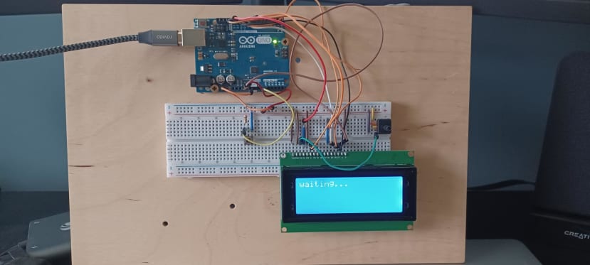
The hardware consists of an Arduino Uno, a single switch with a pull-down resistor, and a standard 4 x 20 backlit LCD with a 10K contrast potentiometer. 5 components and a bunch of wires.
- When the switch is pressed a message gets sent to the PC app.
- The display shows incoming messages from the PC app.
This very simple project established two-way communication between the Arduino and the PC. It can easily be modified to form a range of applications to control Arduinos for test, measurement and any data gathering and control projects.
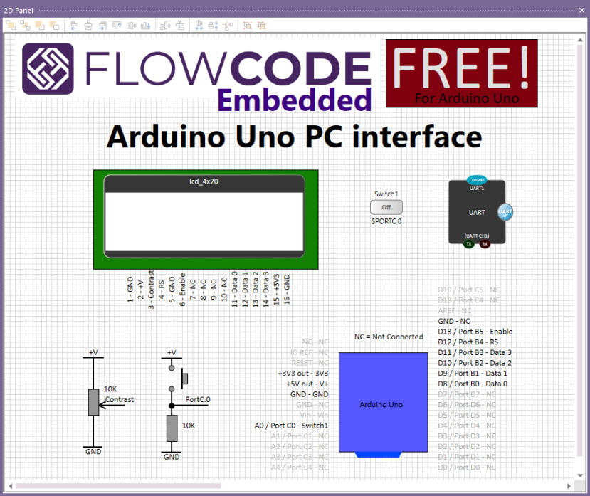
The connections can be seen in the following diagram which is taken from the Embedded program:
The Software
The PC application is developed in FLowcode which is completely free for Arduino Uno.
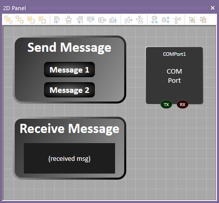
There are two on-screen switches on the app:
- The Message 1 switch sends the message “hello” to the Arduino board.
- The Message 2 switch sends the message “goodbye” to the Arduino board.
There is a Receive Message text field on the app. This displays the value of a variable COUNT when the switch connected to the Arduino is pressed.
This is a basic example that you can easily build to understand how the Embedded program, the PC Developer program and the hardware are all developed and how the software all works. A subsequent project will show you how you can expand on this to create more comprehensive test systems using Arduino Uno and Espressif ESP32 technology like this:
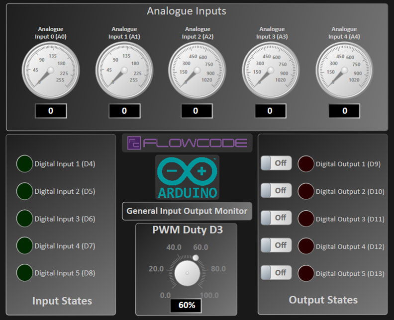
You can then use this system for your own projects.
Arduino Embedded Software App
To get started you can download the free version of Flowcode from www.flowcode.co.uk. When you have installed this start a new Flowcode embedded program with Arduino Uno R3 as the target device.
The goal of this basic example is to send and receive serial data, which requires the use of a UART (RS232) component. The use of an Arduino is really neat here: the Uno has an onboard FTDI device which converts simple serial data to USB so the communication between the PC and the Arduino is really simple.
An LCD component is needed to display received messages and a button switch is used to send messages from the embedded app. The following components need to be placed onto the Flowcode component 2D panel:
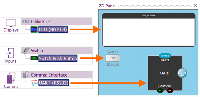
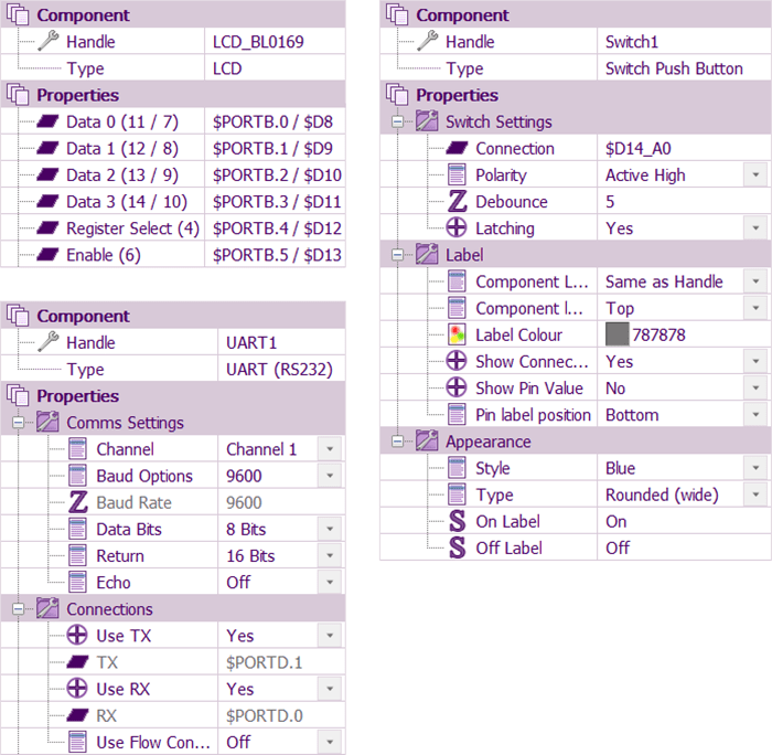
Drag each of these components onto a 2D panel and then set their properties as shown below:
The embedded app will have just a single “Main” macro and use the following global variables:
| Variable | Type | Purpose |
|---|---|---|
| count | Integer | Keeps track of the number of received messages |
| btn | Byte | Reads the state of the switch to detect when it is pressed |
| msg[20] | String[20] | Contains the messages received and to be sent |
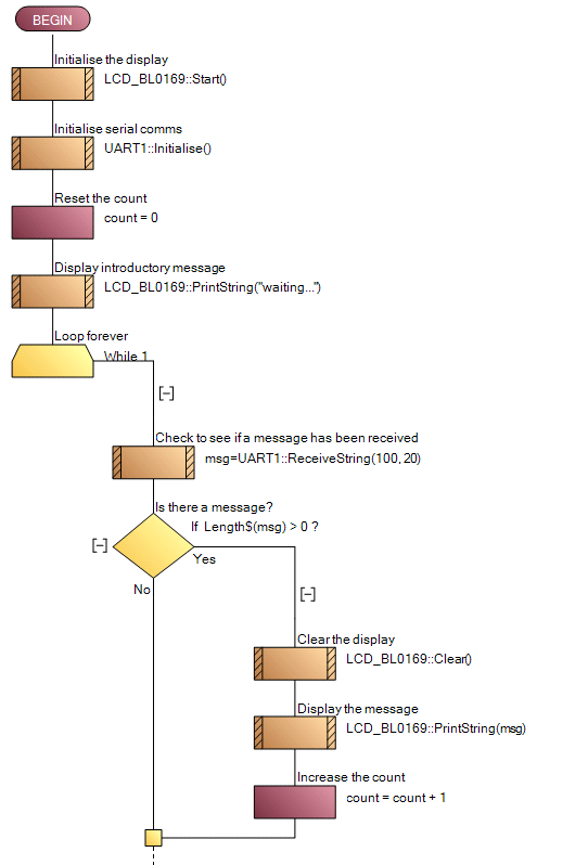
The first half of this macro is shown below:

The first few icons initialise the display and the serial comms components. Following this, an integer variable – ‘count’ – is set to zero and then an introductory message is displayed. The remainder of the Main macro consists of an infinite loop which continually checks for incoming data on the serial port. If any data is detected, the ‘msg’ string variable will be populated with the message and will therefore have a size greater than zero. If this is the case, the LCD is cleared and the message is displayed. The ‘count’ variable increments by one each time an incoming message is detected and displayed.
The remainder of the infinite loop is shown below and enables the sending of messages to the PC. The state of the switch input is first read and if it is currently pressed, a message is created which uses the ‘count’ variable to inform how many messages have been received. This message is sent via the UART component to the PC and then the program flow is halted until the switch state becomes low again – i.e. until the user has released the connected button.
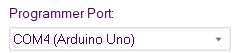
Once this flowchart has been created, the program can be compiled and downloaded to the Arduino using the “Build…Compile to Target” menu item. Remember to specify the port that connects the PC to the Arduino on the “Project Options” screen. The Arduino port will be listed in the appropriate dropdown box:
PC App
The associated PC Developer app will behave in an equivalent way to the embedded app. It will check for incoming data and display it if any is found. It will also send text data out when a button is pressed.
Start a new Flowcode App developer / PC developer program.
The PC app will consist of two buttons to send two different messages and a text field to display any received text. A “COMPort” component is also required, which allows data to be sent to and received from the PC’s serial port.
Here is the design of the basic web app:
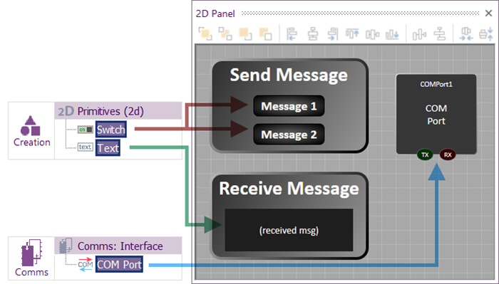
Extra visual styling elements have been added to make the app look nice, but these are not necessary. The four essential components are shown and can be dragged onto a 2D panel from the indicated location in the Components menu of Flowcode.
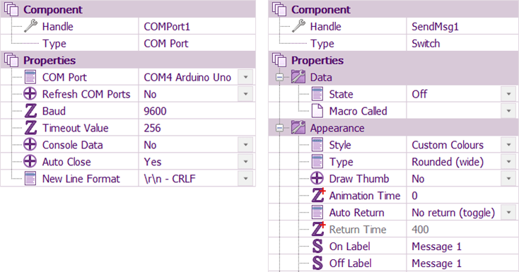
Details of the COMPort component are shown below. The “COM Port” entry needs to be appropriate for your hardware connection. Also shown below is the properties of one of the switches. The properties of the other switch will be the same (except with different label text). The Text component will have no unusual property settings and can retain its defaults.
A single global variable, “msg” is used to receive and display data. This is a string using the default array size [20].
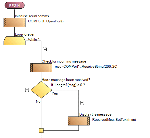
As with the embedded app, there is a single “Main” macro which contains initialisation code followed by an infinite loop which checks for incoming data and for user button presses. The first part of this Main macro is shown below. Notice the check for an incoming message is like the embedded app:
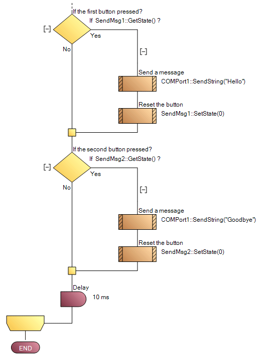
The second half of the infinite loop checks each switch, and a message is sent if a switch has been pressed. After sending a message, the state of the switch is reset so it can be pressed again.
This app can be run from within Flowcode using the “Run” button in the “Debug” menu and if it is working correctly can be deployed as a stand-alone PC app using the File…Export menu.
Conclusion
This simple example shows two projects – an embedded app and a PC-based app – that communicate with each other using the serial port, exchanging text messages between the embedded device and the PC.
They have been developed within Flowcode using similar techniques with just a few components and flowchart commands and can form the basis of much more complex interactions between a PC and an external embedded device.
In part 2 we will be looking at how you can expand on this simple PC interface to make a more comprehensive test and measurement system for your Arduino Uno.
Resources
You can find pre-written Flowcode programs on the Flowcode website at: https://www.flowcode.co.uk/app-developer/free-apps/
Flowcode 10 is now available from the RS website. A free version of Flowode allows users to create programs for selected PIC, Arduino, ESP and RPi devices. Flowcode for professional users is a paid-for licence which includes compilers for 500 embedded devices and professional user benefits.
Buy Flowcode: https://software.rs-online.com/product-category/software/
Flowcode wiki: https://software.rs-online.com/support/

Comments