Motor Bearing Vibration Detection with TE 820M1 Accelerometer
Follow article
 Dave from DesignSpark
How do you feel about this article? Help us to provide better content for you.
Dave from DesignSpark
Thank you! Your feedback has been received.
Dave from DesignSpark
There was a problem submitting your feedback, please try again later.
Dave from DesignSpark
What do you think of this article?
By Mike Donnelly - Principal Engineer at Siemens Digital Industries Software.
Piezoelectric (PE) accelerometers are ideal for industrial condition monitoring and predictive maintenance applications, providing long-term, reliable, and accurate performance. The TE 820M1 (261-8102) accelerometer product family covers a broad acceleration range (±25g to ±6000g), with a flat frequency response up to >10kHz. These devices are suitable for a wide variety of motor-bearing vibration detection applications.
| Range | ±25, ±50, ±100, ±200, ±500, ±6000 (g) |
| Sensitivity | 50, 25, 12.5, 5.0, 2.5, 0.21 (mV/g) |
| Frequency Response | 2Hz – 15kHz (3 dB) |
| Excitation Voltage | 1.5V* to 5.5V (*Operation below 2.8V may limit full scale range) |
Table 1: Product Specifications:
See the TE 820M1 Datasheet for more detailed product information.
The Bearing Vibration Monitor System shown below is a “Live – Tunable” design. You can change any of the system parameters that are shown in blue, to match the specific configuration of your application. Then you can run a new simulation (by clicking on the green “play” arrow) to see the results of those changes.
This application example shows the start-up transient of an induction motor with a fan-load. The design includes a bearing vibration monitor circuit using the TE 820M1 accelerometer, along with an anti-alias RC low pass filter and an analog-to-digital converter. The sampled-data equivalent output voltage is shown on the far right (green waveform).
Choose the right “dash number”:
One of the changes the reader can make is to choose a different "dash number" (or “Suffix”) for the accelerometer part number. For example, double-click on the TE 820M1 and change the dash number from 0100 to 0050, then re-run the simulation (i.e., click the green “play” arrow in the simulation toolbar at the top of the schematic. When the simulation finishes, you’ll see the effect of using a higher sensitivity accelerometer. The accelerometer output voltage (blue waveform) will be increased, from approximately 2Vpk-pk to 4Vpk-pk (Peak-to-peak voltage). If you choose dash number 0025 and run another simulation, the output will increase again, but it will clip on at 0 and 5V rail voltage limits.
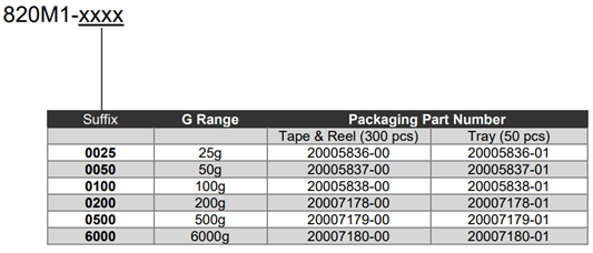
Table 2: Ordering information based on desired application G Range
Choose the right anti-alias filter bandwidth:
Another user-selectable parameter is the capacitance value in the RC filter. It is nominally set at 0.22uF, which together with the 1k Ohm resistor gives a low-pass pole frequency just over 700Hz. The filter prevents high frequency power supply noise from aliasing into the low frequency detection band of the monitor system, appearing as a (false) vibration signal at the sampled output. Since the motor operates at just under 1800 RPM, with a bearing cycle multiple of 20, the expected vibration frequency is just under 600 Hz, so it will pass through the filter as desired. However, there is a 9kHz sinusoidal noise signal on the 5V power supply to the accelerometer. If this is allowed to pass into the ADC, which is sampling at 10kHz, the result will be an apparent 1kHz "false" acceleration signal at the output.
You can see this false signal in the output spectrum if you first double-click on the capacitor and change its value from 0.22uF to 0.022uF and re-run the simulation. Then plot the sampled output voltage (v_sampled_out) in the main waveform viewer and perform an FFT using the built-in calculator function.

Figure 1: Improper RC filter capacitance selection leads to a “false” vibration indicator
*Note: The model used for the TE 820M1 was produced by the author of this example, based solely on information contained in the product datasheet. It has not been verified by the manufacturer.
-
Do you have questions on the above? Ask in the comments section below and Mike is here to help!