Learning Mikroe Clicker 2 - Project 1: Getting Started
Follow project
 Dave from DesignSpark
How do you feel about this article? Help us to provide better content for you.
Dave from DesignSpark
Thank you! Your feedback has been received.
Dave from DesignSpark
There was a problem submitting your feedback, please try again later.
Dave from DesignSpark
What do you think of this article?
 Discover MikroElektronika Clicker 2 for STM32, the Necto Studio development environment and get to grips with Click add-on modules in the first instalment of our Mikroe learning series.
Parts list
| Qty | Product | Part number | |
|---|---|---|---|
| 1 | MikroElektronika Clicker 2 for STM32 MIKROE-1685 | 8829048 | |
| 1 | MikroElektronika USB UART click USB to UART Add On Board, FT232RL - MIKROE-1203 | 8828913 | |
| 1 | MikroElektronika Temp-Hum 4 Click Sensor Interface mikroBus Click Board, HDC1010 - MIKROE-2938 | 1745638 | |
Welcome to Getting Started with MikroElektronika Clicker 2 for STM32. This is the first project in our learning with MikroElektronika series - from beginner to advanced - these projects will help you get started with embedded development for the first time, or if you are an experienced engineer, to familiarise yourself with the Mikroe development environment.
You will learn:
- Necto studio development environment
- Writing a microSDK application in Embedded C
- Integrating external libraries into your application
- Extending the capabilities of your Clicker 2 with add-on Click modules
In this series:
- Project 1- Getting Started with MikroElektronika Clicker 2
- Project 2 - Automate your home
- Project 3 - Build and connect an IoT weather station to the cloud
Getting Started Index
Part 0: Preparation
Part 1: Hello World - Blink the Clicker 2 LED
Part 2: Hello World - UART Communication
Part 3: Temperature and Humidity Sensor
Part 0: Preparation
Download and Install NectoStudio
First, ensure you have downloaded and installed NectoStudio, the MikroElektronika cross-platform IDE. A free 90-day trial is available for evaluation to allow you to get started.
Hardware
To complete this project you will require a MikroElektronika Clicker2 for STM32 and two Mikroe 'Clicks' which are an easy way to add additional functionality to the Clicker 2
- Clicker 2 for STM32
- USB UART Click - provides a UART interface via a Micro USB connection. This will allow you to communicate between the Clicker 2 and your PC/Mac
- Temp&Hum 4 Click - integrated temperature and humidity sensor to help you understand your environment.
Part 1: LED Blink
1.1 Setting up NectoStudio Project
After installing the NectoStudio and registering for your trial license, we need to open NectoStudio and setup the project.
- Click on New Project.
- Enter the project name and choose where the project will be saved.
- Select the appropriate project template - for this example, we will choose the following settings:
- language - mikroC
- template - mikroSDK Application
- project type – Application

- Select an appropriate profile – for now, Clicker 2 for STM32 doesn’t have its own hardware profile in NectoStudio, but that will be added in future updates. For now, we can use any Fusion for ARM / STM32 v8 profile, because they are based on the STM32F407 MCU.
- Select the Fusion for ARM v8 profile and then click on Next and in the next window on Finish.

Upon creating the new project, we will see the default template for creating the mikroSDK 2.0 programs.
1.2 Configuring Clicker 2 outputs
The first thing we need to do is to uncomment the “drv_digital_out.h” code. This allows us to configure a pin as a digital output.
#include "board.h"
#include "drv_digital_out.h"
Next, we need to create two driver objects – one for each LED we want to toggle. You should choose an appropriate name, here we have chosen led1_pin and led2_pin to make our code easier to read.
static digital_out_t led1_pin;
static digital_out_t led2_pin;
1.3 Initialise driver
Within the application_init() function in main.c, we need to initialize driver objects and set the pins on which they are connected.
We will do that with digital_out_init command:
digital_out_init(&led1_pin, PE12);
digital_out_init(&led2_pin, PE15);
You will find the pin numbers PE12 and PE15 marked on the Clicker2 board near next to the LEDs LD1 and LD2.
1.4 Write the application
Finally we need to add our application code within application_task(), this code is run and looped continuously after application_init() has been run. In this simple example we will toggle the LEDs on and off, waiting for 500ms in-between. We will use the digital_out_toggle function, which, as its name suggests – toggles the selected LED pins.
digital_out_toggle(&led1_pin);
Delay_ms(500);
digital_out_toggle(&led2_pin);
Delay_ms(500);
Your code is now complete - just a couple of things to do and the LEDs on your Clicker 2 will start blinking.
Your main.c should now look like this:
/**
* @file main.c
* @brief MikroSDK base application.
*/
#include "board.h"
#include "drv_digital_out.h"
/// @todo Include wanted Driver headers to use.
/// @example
static digital_out_t led1_pin;
static digital_out_t led2_pin;
/// @todo Define Driver objects.
/// @example
static digital_out_t led1_pin;
static digital_out_t led2_pin;
/// @brief Application init function.
void application_init()
{
/// @todo Initialize Driver objects.
/// @example
  digital_out_init(&led1_pin, PE12);
  digital_out_init(&led2_pin, PE15);
}
/// @brief Application task.
void application_task()
{
/// @todo Implement your application code here.
/// @example
  digital_out_toggle(&led1_pin);
  Delay_ms(500);
  digital_out_toggle(&led2_pin);
  Delay_ms(500);
}
/// @brief Application main function.
void main(void)
{
  application_init();
  while (1)
  {
    application_task();
  }
}
1.5 Configuring the clock
Next, we must configure the timing source for the STM32 microcontroller on the Clicker 2 - this is often referred to as the clock.
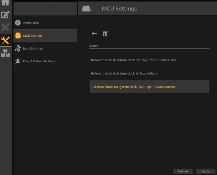
- Navigate to MCU settings - Click on the
icon, choose MCU Settings and click on the Load configuration from scheme template.

- Load the appropriate clock configuration scheme - Select: Referent Clock : 16; System clock:168; Tags: 168MHz internal and press Apply.
1.6 Building the application
We now need to build the code - i.e turn the code into a binary file which is understood by the STM32 microcontroller.
- Click the Hammer icon in the main menu bar to start building your project.

If the project doesn’t have any errors in code, it will build successfully and upon completing the build it will display the following message:

1.7 Programming Clicker 2
Finally we will program the application onto the Clicker 2 development board through the bootloader – here’s how I do it.
- Right-click on the main.c file in the Project Manager window and choose Open file location.
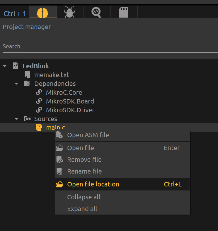
- Go one folder above and find the build-ledblink folder

- In the LedBlink folder, you’ll find the LedBlink.hex file, which we’ll program

- Now let’s open the HID bootloader from Tools menu
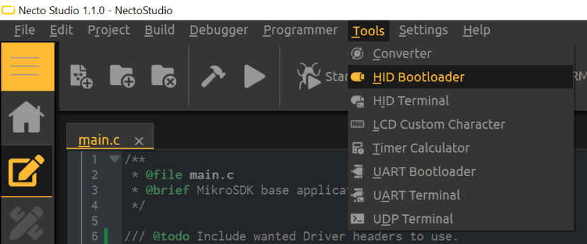
- Connect the USB cable to the development board and turn the Clicker 2 ON.
You’ll see the name of the development board and in the next 5 seconds, it will be connected to the bootloader. Press Reset on the dev board to connect it again, if needed.
- Drag the LedBlink.hex file to the HID Bootloader and you will initialize programming.


After uploading the compiled application to the Clicker 2, the microcontroller will restart and you should see the LEDs blinking on your board.
Success! Well done, you have written your first application for the MikroE Clicker 2
Part 2: Hello World - UART Communication
In the Hello World UART tutorial we will build a simple UART echo application - we will read a received byte from RX(receive) and send it back via TX(transmit). You will test this application by connecting to the USB UART interface from your PC terminal and typing a message which will be retransmitted back.
You will learn how to initialise and working with the UART module inside your MCU using mikroSDK v2.
In order to follow this tutorial, you will have needed to familiarize yourself with context and configuration structures, their purpose and their proper initialization.
Now, regarding Hello World and NectoStudio - we’ll use the same profile settings as in previous LedBlink example, and as we generally use only the UART pins on the mikroBUS socket, we don’t need to change the hardware profile.
2.1 Build the hardware
For this example, we will place USB UART Click Board in the mikroBUS socket 1 on the Clicker 2 dev board.
2.2 Configure project
We need to create a new project, choose the mikroC – mikroSDK Application and assign it to Fusion for ARM v8 profile.
2.3 Writing the application
- Include UART Driver - we need to include the UART driver header file and create a UART driver context structure.
#include "drv_uart.h"
uart_t uart;- Next, we create two variables which we’ll assign to rx and tx UART buffer.
static uint8_t uart_rx_buffer[16];
static uint8_t uart_tx_buffer[16];- We will also create two additional variables – to store additional buffer for receiving and sending back information from the terminal. You will see how these are used later.
static uint8_t buffer[16];
static uint8_t size;
In the UART configuration structure, we are required to state which pins we want to initialize UART on as well as the desired baud rate.
- Declare UART pins - as we are going to use USB UART Click Board on a mikroBUS 1 socket, the pins that we will use are PD6 and PD5.

We will assign them by typing the following command:
uart_pins.rx_pin = PD6;
uart_pins.tx_pin = PD5;- Initialise UART - we now have everything we need to initialise the UART interface. We can initialize UART by using the uart_open() function and passing the context and configuration structures we created as well as selecting a suitable baud rate.
uart_open( &uart, &uart_pins,
      uart_rx_buffer, sizeof(uart_rx_buffer),
      uart_tx_buffer, sizeof(uart_tx_buffer)
     );
uart_set_baud(&uart, 56000);
Now that the UART interface is initialised we are able to use it to transit information.
- Transmit using UART - we can write a command that will display Hello World in the terminal using uart_println(); command.
uart_println(&uart, "Hello World!");We could stop here, but let's add some additional functionality to the code.
- Create echo application - using the uart_read() function we can check if we have received any bytes from the terminal and echo them back by combining with the uart_write() function. Add this code within application_task().
size = uart_read(&uart, buffer, sizeof(buffer));
if(size)
{
  uart_write(&uart,buffer,size);
}
At the end of this example, your main.c should look like this:
/**
 * @file main.c
 * @brief MikroSDK base application.
 */
#include "drv_uart.h"
#include "board.h"
uart_t uart;
static uint8_t uart_rx_buffer[16];
static uint8_t uart_tx_buffer[16];
static uint8_t buffer[16];
static uint8_t size;
/// @brief Application init function.
void application_init()
{
  uart_pins_t uart_pins;
  uart_pins.rx_pin = PD6;
  uart_pins.tx_pin = PD5;
  uart_open( &uart, &uart_pins,
        uart_rx_buffer, sizeof(uart_rx_buffer),
        uart_tx_buffer, sizeof(uart_tx_buffer)
       );
  uart_set_baud(&uart, 56000);
  uart_println(&uart, "Hello World!");
}
/// @brief Application task.
void application_task()
{
  size = uart_read(&uart, buffer, sizeof(buffer));
  if(size)
  {
    uart_write(&uart,buffer,size);
  }
}
/// @brief Application main function.
void main(void)
{
  application_init();
  while (1)
  {
    application_task();
  }
}
2.4 Configuring the clock
As in the previous example, we must configure the timing source for the STM32 microcontroller on the Clicker 2.
- Navigate to MCU settings - Click on the
- Load the appropriate clock configuration scheme - Select: Referent Clock : 16; System clock:168; Tags: 168MHz internal and press Apply.
2.5 Building the application
As demonstrated in Part 1, build the example and program it using the HID bootloader application.
2.6 Testing the application
- Once the application has finished uploading to the Clicker 2, connect an additional cable to the USB UART Click and open the UART Bootloader.
- Select the appropriate COM port and enter the baud rate chosen earlier - 56000bps.
If you have been successful the output on the terminal should look like this:

By typing any character in Send / Input box and pressing Enter on the keyboard - we will send the character to the development board, which will immediately be echoed back in the terminal.
Part 3: Temperature and Humidity Sensor Communicating with PC
3.1 Build the hardware
For the final example of the Getting Started project, we will use the Temp&Hum 4 Click Board and USB UART click. Connect these to the mikroBUS 1 and mikroBUS 2 sockets.
3.2 Configuring the project
- Open the New Project, choose the mikroC and mikroSDK Application and assign it to Fusion for ARM v8 profile.
3.3 Download Library - Temp&Hum 4 Click board
Before we can use the Temp&Hum 4 Click board, we need to download the library from the Packages menu.
- Click on the Packages menu and click on Browse tab – enter "Temp&Hum 4" and when the library is displayed – click on Install. After the library installs – it will be displayed in the Installed tab. From there you can access the various information such as library version, description of the most used functions and example of the code.
On the first screen of the NectoStudio – we can choose option Examples. From that menu, we can access the examples that are bundled with compiler and all examples from the Libraries we downloaded.
Now, we could just open the Temp&Hum 4 example from the Examples menu, but let us write the example from scratch, to learn how to import library to the new example.
3.4 Update Board Configuration File - board.h
We will use both mikroBUS sockets for this example, so we need to change the board.h file and add pins that are connected to mikroBUS 1 and 2 socket. You can change this file in NectoStudio by clicking on the board.h and selecting option Goto Definition. This will open the board.h in new window. From there, comment the previous configuration and copy these lines:
This change of the board.h will allow you to use mikroBUS 1&2 from the Clicker 2 and mikroBUS 3&4 from Mikromedia shield for mikroBUS.
#define MIKROBUS_1 1
#define MIKROBUS_1_AN PA2
#define MIKROBUS_1_RST PE7
#define MIKROBUS_1_CS PE8
#define MIKROBUS_1_SCK PC10
#define MIKROBUS_1_MISO PC11
#define MIKROBUS_1_MOSI PC12
#define MIKROBUS_1_PWM PE9
#define MIKROBUS_1_RX PD6
#define MIKROBUS_1_INT PE10
#define MIKROBUS_1_TX PD5
#define MIKROBUS_1_SCL PA8
#define MIKROBUS_1_SDA PC9
#define MIKROBUS_2 2
#define MIKROBUS_2_AN PA3
#define MIKROBUS_2_RST PE13
#define MIKROBUS_2_CS PE11
#define MIKROBUS_2_SCK PB13
#define MIKROBUS_2_MISO PB14
#define MIKROBUS_2_MOSI PB15
#define MIKROBUS_2_PWM PD12
#define MIKROBUS_2_RX PD9
#define MIKROBUS_2_INT PE14
#define MIKROBUS_2_TX PD8
#define MIKROBUS_2_SCL PB10
#define MIKROBUS_2_SDA PB11
#define MIKROBUS_3 3
#define MIKROBUS_3_AN PC3
#define MIKROBUS_3_RST PA6
#define MIKROBUS_3_CS PA7
#define MIKROBUS_3_SCK PB13
#define MIKROBUS_3_MISO PB14
#define MIKROBUS_3_MOSI PB15
#define MIKROBUS_3_PWM PB9
#define MIKROBUS_3_RX PA1
#define MIKROBUS_3_INT PD3
#define MIKROBUS_3_TX PA0
#define MIKROBUS_3_SCL PB10
#define MIKROBUS_3_SDA PB11
#define MIKROBUS_4 4
#define MIKROBUS_4_AN PB1
#define MIKROBUS_4_RST PE1
#define MIKROBUS_4_CS PE2
#define MIKROBUS_4_SCK PB13
#define MIKROBUS_4_MISO PB14
#define MIKROBUS_4_MOSI PB15
#define MIKROBUS_4_PWM PB8
#define MIKROBUS_4_RX PA1
#define MIKROBUS_4_INT PD1
#define MIKROBUS_4_TX PA0
#define MIKROBUS_4_SCL PB10
#define MIKROBUS_4_SDA PB11
3.5 Configuring Libraries
- In the Project manager window, right-click on the Dependencies.

This will open a Library Manager
- Select the Temp&Hum4 Click and Log library.

Now in the dependencies tab we’ll see Click.TempHum4 and MikroSDK.LOG listed. These two components are very important for our example.
3.6 Writing the Application
- Include header files for Temp&Hum4 and Log with these lines:
#include "log.h"
#include "temphum4.h"- Declare two instances of temphum4_t and log_t objects:
static temphum4_t temphum4;
static log_t logger;- Within the application_init() function in main.c, we need to configure and initialize log and temphum4 objects
  log_cfg_t log_cfg;
  temphum4_cfg_t cfg;
  // Logger initializatoin
  log_cfg.level = LOG_LEVEL_DEBUG;
  LOG_MAP_USB_UART( log_cfg );
- Declare the RX and TX pins – as the USB UART is now in MikroBUS 2 socket – we will assign PD9 and PD8 pins.
  log_cfg.rx_pin = PD9;
  log_cfg.tx_pin = PD8;
  log_init( &logger, &log_cfg );
log_info( &logger, "Application init");- Now before we write the application, we are left with configuration and initialization of temphum4 context object – we will call temp_cfg_setup(), load the default values and as Temp&Hum 4 Click is in mikroBUS 1, assign MIKROBUS_1 in the code:
  // TempHum4 Click initialization
  temphum4_cfg_setup( &cfg );
  TEMPHUM4_MAP_MIKROBUS( cfg, MIKROBUS_1 );
  temphum4_init( &temphum4, &cfg );
temphum4_default_cfg( &temphum4 );- Within the application_task() function, we will write the code that will get the values from the sensor and send it by UART protocol to the PC terminal.
We need to declare two float variables to hold the values:
  float temperature;
  float humidity;
- After that, we will call functions temphum4_get_temperature() and temphum4_get_humidity() save the values within the temperature and humidity variables we created.
- We will use log_printf(); function to send the data to the Terminal. log_printf() is a similar function to printf(); but in NectoStudio is used to send data via the UART protocol.
- Add a 1-second delay - we will add a 1 second delay at the end of the task so that the sensors are sampled and values printed once a second.
  temperature = temphum4_get_temperature( &temphum4 );
  log_printf(&logger, "Temperature : %f C \r\n", temperature);
  humidity = temphum4_get_humidity( &temphum4 );
  log_printf(&logger, "Humidity : %f %% \r\n", humidity);
  Delay_ms(1000);
At the end, your main.c code should look like this:
/**
 * @file main.c
 * @brief MikroSDK base application.
 */
// Includes
#include "temphum4.h"
#include "board.h"
#include "log.h"
// Variables
static temphum4_t temphum4;
static log_t logger;
/// @brief Application init function.
void application_init()
{
  log_cfg_t log_cfg;
  temphum4_cfg_t cfg;
  // Logger initializatoin
  log_cfg.level = LOG_LEVEL_DEBUG;
  LOG_MAP_USB_UART( log_cfg );
  log_cfg.rx_pin = PD9;
  log_cfg.tx_pin = PD8;
  log_init( &logger, &log_cfg );
  log_info( &logger, "Application init");
  // TempHum4 Click initialization
  temphum4_cfg_setup( &cfg );
  TEMPHUM4_MAP_MIKROBUS( cfg, MIKROBUS_1 );
  temphum4_init( &temphum4, &cfg );
  temphum4_default_cfg( &temphum4 );
}
/// @brief Application task.
void application_task()
{
  float temperature;
  float humidity;
  temperature = temphum4_get_temperature( &temphum4 );
  log_printf(&logger, "Temperature : %f C \r\n", temperature);
  humidity = temphum4_get_humidity( &temphum4 );
  log_printf(&logger, "Humidity : %f %% \r\n", humidity);
  Delay_ms(1000);
}
/// @brief Application main function.
void main(void)
{
  application_init();
  while (1)
  {
    application_task();
  }
}
3.7 Configuring the clock
As in the previous example, we must configure the timing source for the STM32 microcontroller on the Clicker 2 - we will continue to use the 168MHz internal clock.
3.8 Building and upload the application
As before, build the example and program it using the HID bootloader application.
3.9 Testing the application
- Once the application has finished uploading to the Clicker 2, connect an additional cable to the USB UART Click and open the UART Bootloader.
- Select the appropriate COM port and enter the baud rate chosen earlier - 9600bps.
You will see the displayed values of temperature and humidity in the terminal. By placing the finger over the sensor of the Temp&Hum 4 Click – you’ll see how the displayed value changes.

Congratulations! If you have completed all of the stages of this tutorial you have built your first three basic applications, and learnt how to incorporate microSDK libraries with your application.
Stuck? If you experienced difficulties with any part of the project comment below for support from the Designspark community.
Comments