Measuring 4-20 mA Current with Digilent MCC DAQ Devices
Follow articleHow do you feel about this article? Help us to provide better content for you.
Thank you! Your feedback has been received.
There was a problem submitting your feedback, please try again later.
What do you think of this article?
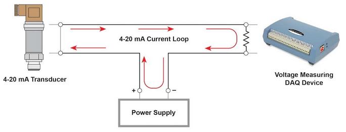
The 4-20 mA current loop interface revolutionized information transmission over long distances, offering an effective alternative to voltage signals prone to noise and voltage drops along wires. Primarily used for measurements or control purposes, this technology finds applications in scenarios where data must be transmitted across vast distances. For instance, in a factory setting, transmitting pressure values from a remote location to a control room hundreds of feet away is achieved seamlessly through the 4-20 mA current loop. Similarly, the control room can adjust the pressure by sending a 4-20 mA signal back to the pressure controller, maintaining a reliable and efficient communication link.
Current Monitoring Instruments:
Instruments designed to monitor current levels employ a precision resistor to convert the current to voltage. The widely used 250-ohm resistor ensures a 1 to 5 VDC voltage drop. For optimal performance, the resistor must have a 0.1% tolerance (or better), a minimum power rating of 0.25 W, and a temperature coefficient of at least 25 ppm/°C. Alternatively, lower resistance values like 62.5 ohms [for a reduced voltage drop within the loop of 0.25 to 1.25 VDC] are used, demanding that the instruments can accurately measure such low values. When dealing with a fixed 5-volt input, the 250-ohm resistor provides the best accuracy, as the voltage span covers most of the range.
Understanding Ohm's Law:
Ohm's Law dictates that the voltage across a resistor is the product of the current flowing through it and the resistance itself.
voltage = current x resistance, or volts = amps x ohms, or V = A x Ω.
Powering the Loop:
4-20 mA transducers typically require an excitation voltage between 9 and 30 volts. To avoid errors at the upper range, the excitation voltage must exceed the sum of all voltage drops in the loop, including those along the wires. If multiple monitoring processes exist in the loop, choosing an excitation voltage greater than 10 volts is recommended. Power supplies with values between 18 to 24 volts are commonly preferred for reliable performance.
Selecting Input Type:
For optimum results, using a differentially-ended input across the resistor is ideal. However, single-ended inputs can also be employed with caution to avoid ground loops. In situations where the power supply negative serves as the system ground and the DAQ and meter are isolated, single-ended connections work well. Nonetheless, if the DAQ device lacks isolation and derives its ground from the computer, there might be a voltage difference between it and the power supply negative. In such cases, utilizing a differential connection is the best practice. For substantial differences between the negative and computer ground, a DAQ device with isolation capabilities should be used.
Consideration for Measurement Location:
The measurement location within the loop warrants careful attention. If the DAQ input is sensitive to common mode voltage, placing it as close to the ground as possible is advisable. In other sections of the loop, the inputs may experience 5 volts or more of common mode. For these scenarios, isolated inputs prove to be the most effective solution.


