Is there an example of how external 3D models integrate into a DSM project?
Follow tutorial
 Dave from DesignSpark
How do you feel about this tutorial? Help us to provide better content for you.
Dave from DesignSpark
Thank you! Your feedback has been received.
Dave from DesignSpark
There was a problem submitting your feedback, please try again later.
Dave from DesignSpark
What do you think of this tutorial?
This tutorial requires:
DesignSpark Mechanical V6.0Follow these steps using an example part to find out 3D models from our online catalogue (like TraceParts) can be integrated into a DSM project.
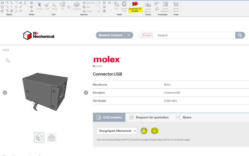
Open the 3D model library via the Design tab in the software. Then, search for this manufacturer part number: 67068-8001
Click on the top result and either download to a folder or insert directly into DSM (options highlighted).
Working with imported 3D model in DSM
Now that you have the external 3D model, let’s make a cut-out of it in a solid, like how you would make peripheral ports for an electronics enclosure.
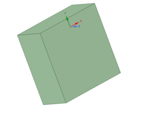
1. Create a cube of 20mm x 20mm x 10mm.
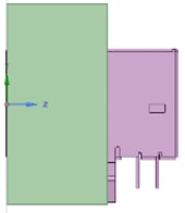
2. With the Move tool, manoeuvre the connector into the panel with only the input touching the top surface.
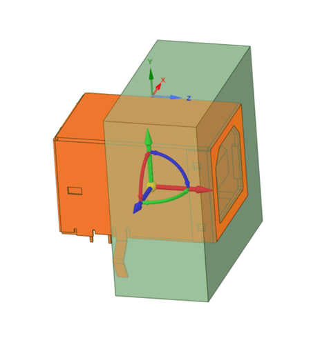
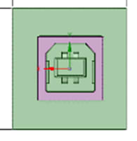
3. Select the Combine tool. Left-click on the panel once and then click on the USB connector. The USB connector acts like a cutter carving its shape through the panel.
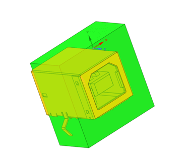
4. Triple click on the panel remnant lodged in the connector input and Delete. Highlighted orange in below:
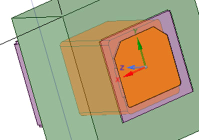
5. Once completed, the embedded connector should look like this (front face & right face profiles shown).