Is there an example of how external 3D models integrate into a DesignSpark Mechanical project?
Follow tutorialHow do you feel about this tutorial? Help us to provide better content for you.
Thank you! Your feedback has been received.
There was a problem submitting your feedback, please try again later.
What do you think of this tutorial?
This tutorial requires:
DesignSpark Mechanical V6.0Follow these steps using an example part to find out 3D models from our online catalogue (like TraceParts) can be integrated into a DesignSpark Mechanical project.
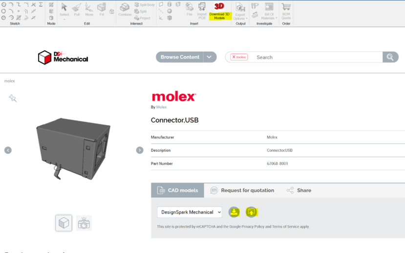
Open the 3D model library via the Design tab in the software. Then, search for this manufacturer part number: 67068-8001
Click on the top result and either download to a folder or insert directly into DesignSpark Mechanical - DSM (options highlighted).
Now that you have the external 3D model, let’s make a cut-out of it in a solid, like how you would make peripheral ports for an electronics enclosure.
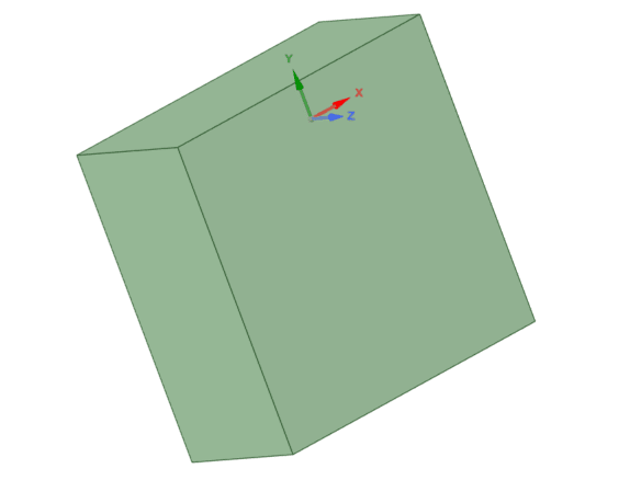
1. Create a cube
Create a cube of 20mm x 20mm x 10mm.
2. Move the Model
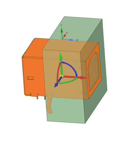
Manoeuvre the connector into the panel with only the input touching the top surface.
3. Combine tool.
Left-click on the panel once and then click on the USB connector. The USB connector acts like a cutter carving its shape through the panel.
4. Remove Remanent
Triple click on the panel remnant lodged in the connector input and Delete.
Highlighted orange in below:
5. Completed Profiles
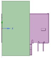
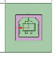
Once completed, the embedded connector should look like this (front face & right face profiles shown)


