How to configure a Guardlink System
Follow article
 Dave from DesignSpark
How do you feel about this article? Help us to provide better content for you.
Dave from DesignSpark
Thank you! Your feedback has been received.
Dave from DesignSpark
There was a problem submitting your feedback, please try again later.
Dave from DesignSpark
What do you think of this article?
Guardlink is a very simple system to configure and use. It is made up of three main parts.
Safety Relay
The 440R-DG2R2T – This safety relay, is the master control unit for the system, it has two Guardlink channels, each of which can monitor up to 32 safety devices.
Ethernet Gateway
The 440R-ENETR gateway provides the link between Guardlink and the control system. Real-time diagnostic information is communicated from Guardlink, and reset signals and lock/unlock commands can be communicated from the control system.
Smart Taps
The smart taps connect the safety input devices to Guardlink. There are four available.
5 pin and 8 pin smart taps are available for input devices with OSSD outputs, such as RFID non-contact switches, and 5 pin and 8 pin smart taps are available for input devices, which have volt free contacts such as emergency stop push-buttons.
Configuring the system
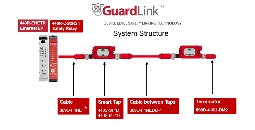
Every system, as a minimum, needs:
- A 440R-DG2R2T safety relay
- A 440R-ENETR Ethernet Gateway
- A Smart Tap for each safety input device
- An 898D-418U-DM2 system terminator plug (for the last Smart tap on the system), and
- Cabling as required
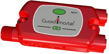
Guardlink Smart Taps
Each input device requires a smart tap for connection to Guardlink.
If the input device has OSSD outputs then the following smart taps can be selected:
- 440S-SF5D – for 5 pin devices
- 440S-SF8D – for 8 pin devices
If the input device has volt-free contacts then the required taps are
- 440S-MF5D – for 5 pin devices
- 440S-MF8D – for 8 pin devices
A technical file confirming which tap is needed for each input device can be found on each Smart Tap page on RS, e.g. (190-2124) .
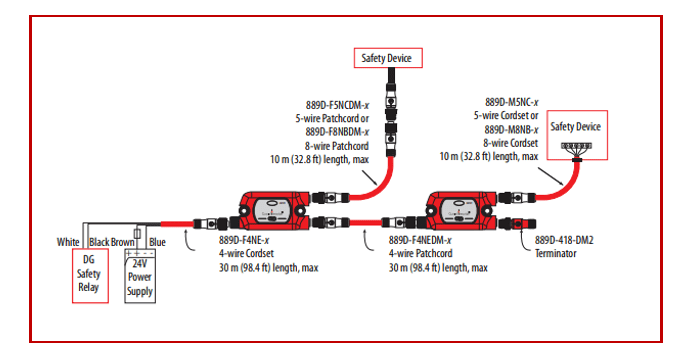
Cable selection
Cables for Guardlink need to be selected from the safety relay to the first smart tap, from each smart tap to the input device, and between the smart taps.
When selecting the 440R-DG2R2T, or the Smart taps from the RS Components website, the recommended cables are also shown.
The image below shows the generic cable references, the only addition required is the length of each cable.
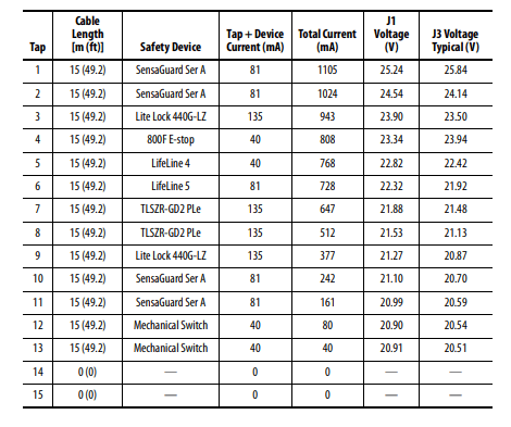
Finally, once the parts are selected, the volt drop and current consumption of the Guardlink system needs to be considered.
Guardlink requires a voltage level from between 20.4 to 26.4V d.c. (0.85 to 1.1 x 24Vd.c.) and a maximum current of 4 Ampere per system must not be exceeded.
The GuardLink Voltage Drop calculator v2 02.xlsx file makes this check easy to carry out and can be found on the 440R-DG2R2T web page on RSwww.com
The file has drop-down menus for connected products, and the supply voltage and cable type can be adjusted to suit.
The length of cable to each input device can also be changed to suit the system being developed.
The table below is for a supply voltage of 26V d.c.
This document provides the basic information on the process of putting a Guardlink system together, the user manual should always be referred to for full technical information and can be found on the web page for the 440R-DG2R2T safety relay.
Comments