How to build an Arduino Micro LCD Game Console
Follow articleHow do you feel about this article? Help us to provide better content for you.
Thank you! Your feedback has been received.
There was a problem submitting your feedback, please try again later.
What do you think of this article?
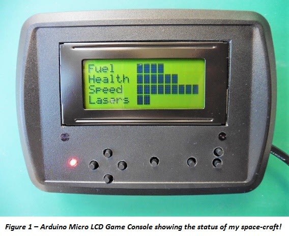
have always wanted to build a hand-held game console which I could use to program my own games, and this was the inspiration for my latest project the Arduino Micro LCD Game Console. If you are interested in the Arduino and like to play games, then you might want to create something similar by following the ideas in this blog.
Warning!- This blog assumes that you have some knowledge about electronics and programming the Arduino, and that you are experienced in using tools and a soldering iron. However, even if you are not I hope that you find reading the blog of interest anyway. The author accepts no responsibility for any errors, omissions (or accidents!) if you decide to re-create this design.
Some early computer games were text driven adventure games that you could play on a home computer, the type which relied upon your imagination to navigate your way through some fantasy land or travel through space and complete a quest. These are the types of games that I would like to eventually emulate on my games console, but I would also like to experiment and try to create some arcade style games with some basic graphics.
The first task was to design and build the hand-held console. I could have chosen a graphical LCD or OLED display, but I wanted a display that used a standard and easy to use Arduino library. So I chose a 16-character x 4-line LCD display which uses the standard Arduino LCD library. This type of display will only allow you to create eight basic graphic characters at a time, however it will be fine for the type of games that I want to design. I also chose the Arduino Micro at the heart of the design because it is small enough to fit in the enclosure and still allows additional components to be added at a later date.
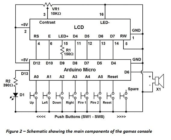
The circuit diagram for the Games Console is shown in Figure 2 below.
After creating a design for my project I managed to salvage some of the parts and equipment wire from my workshop, some of the other items I purchased from RS Components, the parts list with some suggested RS part numbers is shown below -
|
Code |
RS Part Number |
Description |
Quantity* |
|---|---|---|---|
|
Hardware |
Black ABS Handheld Case |
1 |
|
|
LCD |
16 x 4 Character Liquid Crystal Display |
1 |
|
|
Hardware |
Stripboard |
1 |
|
|
SW1-8 |
Push button switch |
8 |
|
|
D1 |
3mm Red LED |
1 |
|
|
Arduino |
Arduino Micro without headers |
1 |
|
|
Cable |
USB cable (0.8m) |
1 |
|
|
Hardware |
M2 nylon screws |
6 |
|
|
Hardware |
M2 nylon nuts |
24 |
|
|
X1 |
Piezo sounder |
1 |
|
|
Hardware |
20 way PCB header pins |
1 |
|
|
VR1 |
10KΩ variable resistor |
1 |
|
|
R1 |
150Ω 0.5 watt carbon film resistor |
1 |
|
|
R2 |
390Ω 0.5 watt carbon film resistor |
1 |
*Note – Some components are sold in packs or multiples that exceed the number required for this project
The steps that I took to build the game console are outlined below.
Step 1 – Modifying the enclosure & fitting the LCD
Having found a suitable place to mount the LCD in the lid of the enclosure, I used a drill to create some mounting holes and used a hacksaw blade to cut a rectangular hole for the LCD to protrude through. The LCD was mounted onto the lid of the enclosure using some M2 nylon screws and nuts. Four of the M2 nylon screws were glued into the lid as you can see in Figure 3.
Step 2 – Fitting the stripboard

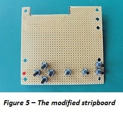
Figure 5 – The modified stripboard with the four directional, and two fire button switches fitted, plus the 3mm LED. A reset and spare button are fitted towards the right hand side of the board
Step 3 – Mounting the Arduino Micro

Step 4 – Wiring everything together
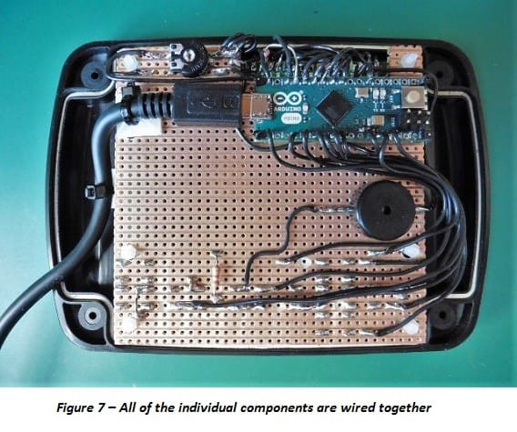
Now is the task of connecting the Arduino board, the LCD and the other components together using instrument wire and by following the schematic. You will see in Figure 7 that I soldered flexible wire to the various components, LCD, push buttons and LED. You will need to make sure that you create breaks in the copper tracks of the stripboard where required so that components do not short out. I also soldered a piezo buzzer to the stripboard (making sure there was a break in the track underneath it) and wired this to the Arduino. This component will allow me to incorporate some basic sounds to my games. I also plugged a USB cable into the connector of the Arduino Micro board and then secured it to the stripboard, using a sticky pad and a cable tie.
Figure 7 – All of the individual components are wired together to complete the console. The variable resistor VR1 is in the top left hand corner and the piezo sounder X1 is just below the Arduino board
Figure 7a – A close-up showing some of the breaks in the copper tracks in between the switches
An additional sticky pad and cable tie are mounted on the lid to help secure the USB cable, and then a small gap was cut into the body of the enclosure to allow the cable to escape as shown in Figure 8. The enclosure can then be screwed to the lid.
Step 5 – Test Sketch
Once everything was complete I created a test program (or sketch) using the Arduino IDE to test the operation of the various components of the console. You can download the Arduino sketch called ‘LCD_Handheld_Game’ here, and use the Arduino IDE to download the sketch into the game console via the USB cable.
If everything is wired correctly, then pressing the various buttons produces some text on the LCD and also illuminates the red LED and creates a noise on the piezo sounder. If the console does not respond in this way, then remove power immediately and check that everything has been wired up correctly. You might also need to adjust the contrast of the LCD so that you can see the text by adjusting the variable resistor VR1.
Now that I’ve built my hand-held games console I can’t wait to start creating some games!


