How can I create my own schematic symbol?
Follow tutorial
 Dave from DesignSpark
How do you feel about this tutorial? Help us to provide better content for you.
Dave from DesignSpark
Thank you! Your feedback has been received.
Dave from DesignSpark
There was a problem submitting your feedback, please try again later.
Dave from DesignSpark
What do you think of this tutorial?
This tutorial requires:
DesignSpark PCB V11.0.0Schematic symbols may be created directly without the use of the wizards. This is straight forward and convenient when only a few connections are required, but the 'Wizards' are more recommended for larger pin counts or when a standard component is required.
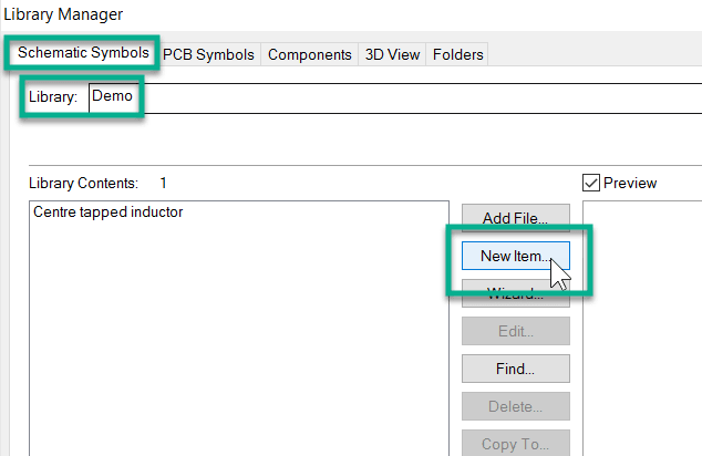
1. Launch library manager
Launch the Library Manager, select the Schematic tab and select the target folder and then click the 'New Item' button.
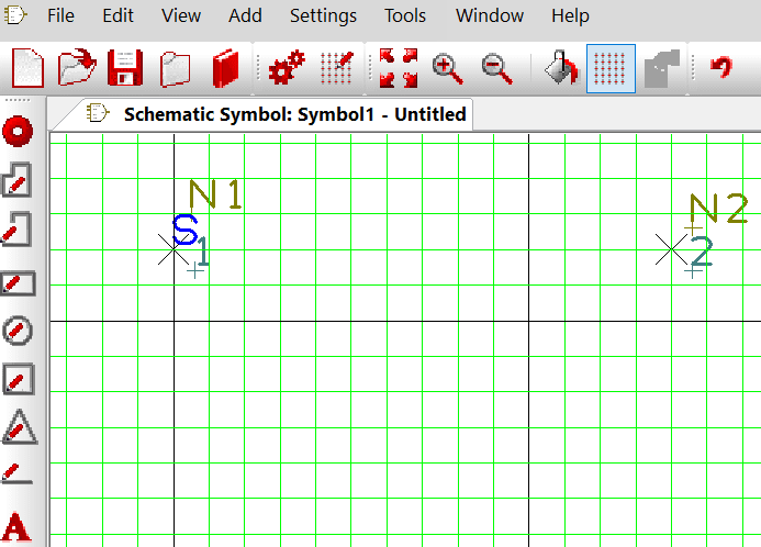
2. Add terminals
The editor screen opens, add your 'terminals', these are the 'pads' on the tool bar for the symbol, (leave your 'style' set as terminal) and place the pads as required at the correct spacing for the schematic symbol. This is actually all that is required by DesignSpark PCB for the connectivity.
3. Create component
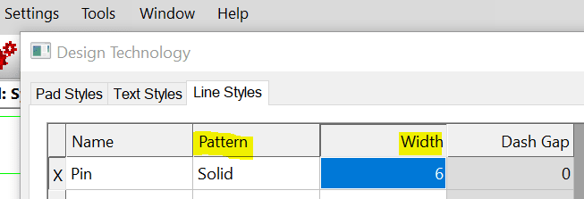
You may now add your symbol 'artwork' to create your component using the 'shape ' tools from the tool bar.
Use line styles to be consistent with your other library components and this can be changed in Settings>Design Technology>Line Styles. The line style currently in use will be marked by an ‘X’ next to it and you can change its width and pattern.
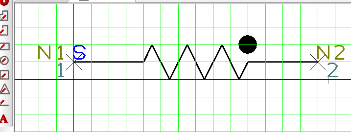
4. Finalise
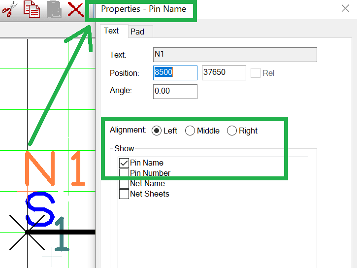
Finally tidy up your design as shown above to position the pin name and number in the correct locations. Select the item, choose 'properties' and choose the appropriate alignment.
The symbol is now complete, save it in the required schematic library.