Hands-on with the Connected Lighting Platform
Follow article
 Dave from DesignSpark
How do you feel about this article? Help us to provide better content for you.
Dave from DesignSpark
Thank you! Your feedback has been received.
Dave from DesignSpark
There was a problem submitting your feedback, please try again later.
Dave from DesignSpark
What do you think of this article?

Setting up the development tools and exploring the examples provided with the onsemi kit.
In a previous post we took a first look at the LED lighting development (201-3383) platform which includes array of features to get you up and running faster in evaluation and prototyping. Such as dual independent LED channels, a Blueooth 5 SoC with FreeRTOS based firmware and examples, together with accompanying Android and iOS apps, and optional PoE (201-3384) .
In this post we’ll now take a closer look at the provided development tools, SDK and example apps. The onsemi IDE is based on the highly popular open source Eclipse IDE. This is extended by Arm CMSIS (Cortex Microcontroller Software Interface Standard) packs, which provide support for the ON Semiconductor RSL10 SoC, FreeRTOS and Bluetooth.
Documentation
The steps described in this post we’re taken from the following documents:
- Connected Lighting Platform Getting Started Guide
- Bluetooth Low Energy IoT Development Kit (B-IDK) Getting Started Guide
- RSL10 Getting Started Guide
Note that the 2nd document was created to accompany the BDK−GEVK kit, which was designed for evaluating the RSL10 SoC. This is a different board, which features Arduino compatible headers, and its documentation is referred to for installing common elements of software support.
The above linked documentation and other official onsemi resources should be seen for comprehensive and authoritative details.
Hardware setup
The hardware setup is pretty straightforward and rather than using the mains power supply included in the CLP kit, the optional PoE board was used instead. Since only a IEEE802.3at a.k.a. PoE+ Ethernet switch was available, this meant that the LED strips could not be fully driven, since the higher powered IEEE802.3bt would be required for this. However, the 25.5W available with 802.3at is more than sufficient for most evaluation and development purposes.
The LED driver board was plugged into the PoE board and this also had the RSL10 module fitted. Then the dual LED strip board was plugged into the other end of the driver board.
Bluetooth Low Energy Services
The RSL10 SoC is at the heart of the Connected Lighting Platform and the SDK by default provides the following Bluetooth Low Energy (BLE) services:
- Light Control Service
- Allows dimming for LED channels
- Telemetry Service
- Reports variables such as system voltage and LED channel current
- PoE Powered Device (PD) Service
- PD Class Characteristic that reports the power level of the platform
- PSE Class Characteristic that changes depending upon the PoE source
- PSE PD Class Override
- Allows power limits to be disabled and available when using 2-pair 802.3at injectors
In the demos we’ll see all of these, apart from the last — PSE PD Class Override — in action.
Out-of-the-box demo
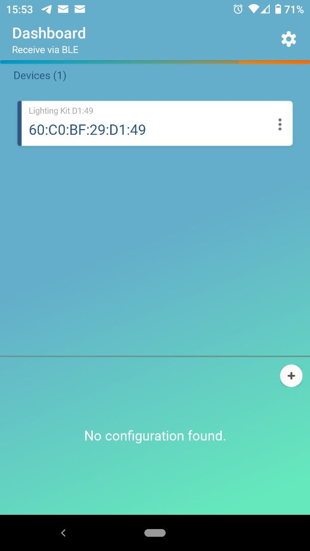
The kit comes supplied pre-programmed and we can proceed with evaluation immediately, by simply installing the RSL10 Sense and Control app. Once started and we have selected “Receive via BLE”, the home screen will list the discovered devices.
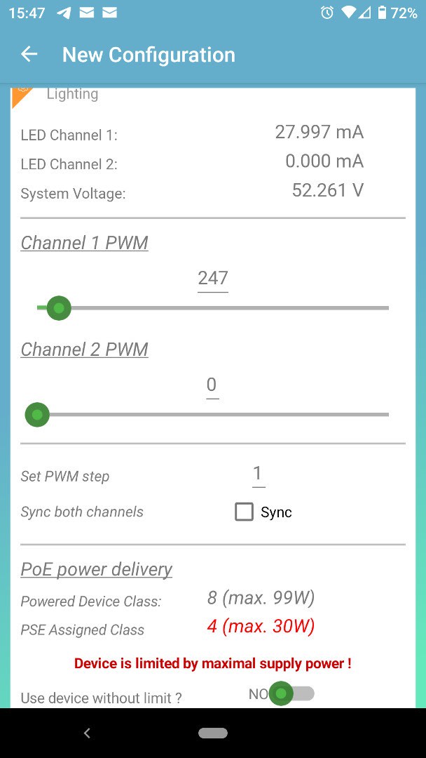
We can then click on our device and the default view provides details of system voltage and LED channel current, and if we are using PoE, the device class information. From this screen, we can also set the brightness/dimming via sliders for the LED channels.

If we swipe left a 2nd screen provides a plot for each channel, showing the PWM duty cycle and LED current vs. time.
In the video below we can see the effect of adjusting the sliders for each LED channel.
Next, let’s take a look at setting up the development environment.
Software setup
The prerequisites for developing for the Connected Lighting Platform are stated in its Getting Started Guide as being:
- Bluetooth® IoT Development Kit CMSIS Pack (01.11.02 or higher)
- onsemi IDE Installer
- RSL10 Software Package
- RSL10 Software Apps Package
- RSL10 Getting Started Guide
- Connected Lighting Platform FOTA Firmware (Optional)
Downloads for these can be found linked on the product page.
In addition to which the following dependencies are specified:
- 64-bit version of Java
- J-Link Version 6.32i or later
- Arm CMSIS pack 5.5.1 or higher
- Arm CMSIS FreeRTOS version 10.2.0 or higher
Finally, if we wish to use the J-Link probe to programme flash, we will also need to install the RSL10 Software Utility Apps.
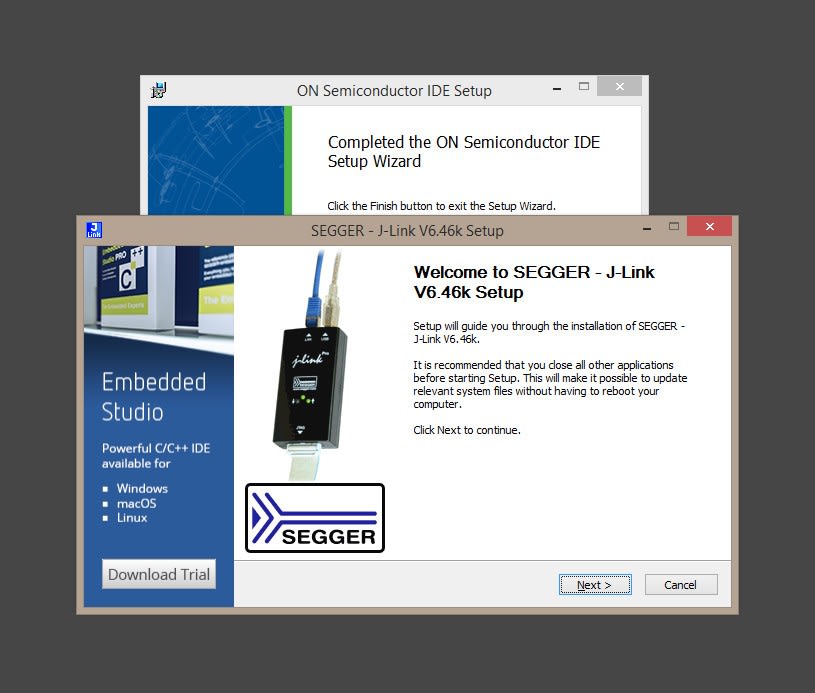
So if we start by installing the IDE and upon running the installer, if we don’t already have the SEGGER J-Link software installed, we will be given the option of installing this.
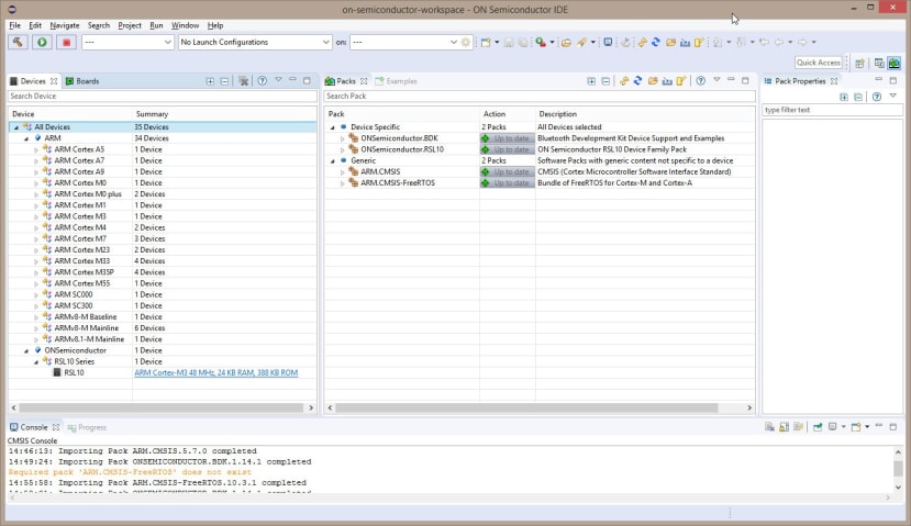
With the IDE installed we can proceed to installing the four CMSIS packs. On the top right corner of the Workbench perspective, click on the Open Perspective icon, select CMSIS Pack Manager, and click Open. Some of these are dependent upon others and so the order to install them is:
- Arm CMSIS
- Arm CMSIS FreeRTOS
- RSL10 CMSIS (RSL10 Software Package)
- BDK CMSIS (Bluetooth IoT Development Kit)
Successful installation will be confirmed in the console window, e.g. “Importing Pack onsemi RSL10.3.3.75 completed”. If we install these in the wrong order we will get an error message telling us that a required pack is not installed.
Assuming everything has gone as planned, we can now proceed to build applications.
Building examples

If we select the Bluetooth Development Kit (BDK) in the Packs tab, we can then navigate the provided examples in the Pack Properties tab. An example can be imported into the IDE by selecting it, right-clicking, and then selecting Copy.

Above we can see the Energy Harvesting Switch Receiver example that has been imported. To access the documentation we double-click on the readme.html file in the Project Explorer. To build the project we simply click on the hammer icon in the toolbar.
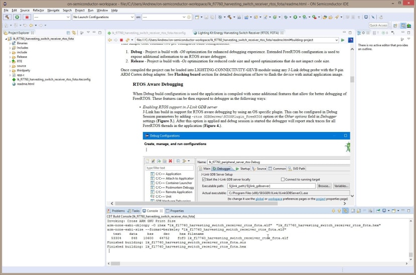
When the build has finished we should see a message similar to the one shown above. Note that pre-built examples are also available in the download named, Connected Lighting Platform FOTA Firmware, which is available from the above linked product page,
Programming
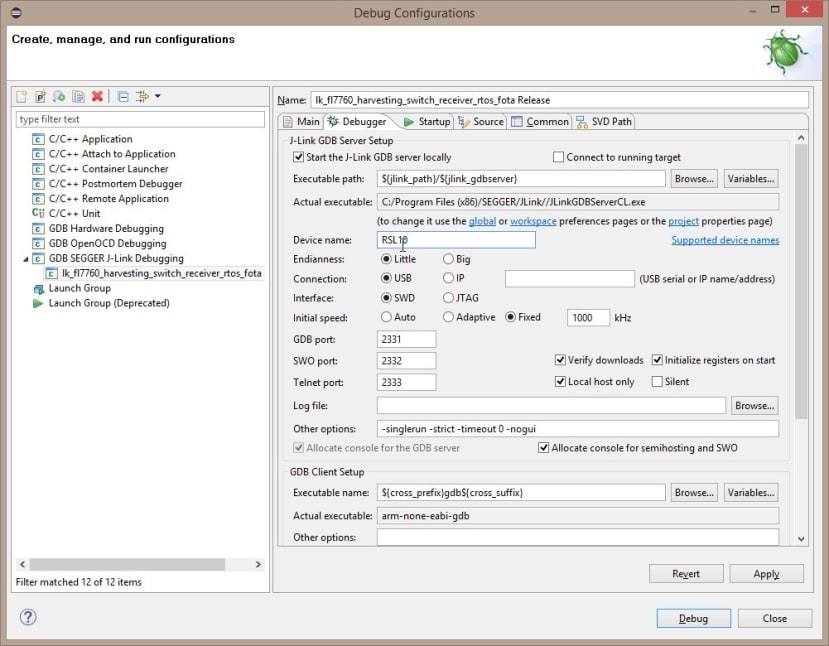
Provided that we have a J-Link interface at this point we could configure the debugger, launch the application and use GDB to debug it. However, if the firmware which is presently loaded on the device has FOTA (firmware over the air) support, we can program it via the RSL10 FOTA app for Android or iOS, else if we have an RSL10 USB dongle (180-6980) from Windows.
We’ll start by taking a look at FOTA.
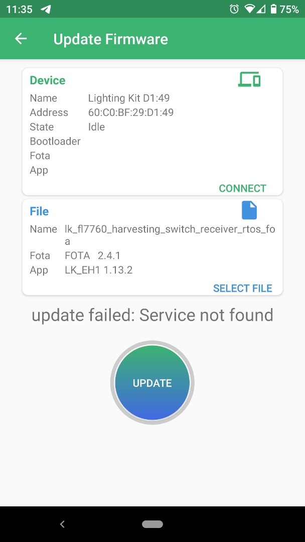
Now if we try this with the CLP as supplied, it is possible that it will fail, since as the Getting Started Guide notes, “Connected Lighting Platform hardware with LOT:SK19450001 will not support FOTA off-the-shelf”. Hence it appears that earlier firmwares which initially shipped with kits did not have FOTA built-in. Later ones may do, but if an error is received, as shown above, it’s likely that the device will have to be first programmed via JTAG with a FOTA-enabled firmware.
To program the RSL10 over JTAG we need a SEGGER J-Link ULTRA+ (131-1321) and the 9-pin Cortex-M adapter (131-1329) . In addition, to use with IDE debugging, we can also use this with the RSL10 Stand-Alone Flash Loader, which is provided along with a similar utility for use with the RSL10 USB dongle and FOTA, as part of the RSL10 Software Utility Apps package.

The Flash Loader is very straightforward to use and with this it was possible to load the energy harvesting switch example.
Following which the onsemi BLE energy harvesting switch module (186-1254) could be paired and then used to dim the LEDs.

Finally, with a FOTA-enabled firmware loaded it was then possible to use the smartphone app to update the firmware over Bluetooth.
Wrapping up
The Connected Lighting Platform provides everything you need to evaluate onsemi devices for use in next generation smart lighting solutions, and following which to expedite prototyping. The kit is well thought out, with a neat modular hardware design and excellent software support, not just in terms of the SDK and examples, but companion apps also.
Comments