Getting Started with the Versatile Revolution Pi Modular Industrial Platform
Follow articleHow do you feel about this article? Help us to provide better content for you.
Thank you! Your feedback has been received.
There was a problem submitting your feedback, please try again later.
What do you think of this article?
Learning the basics with a RevPi Core 3, RevPi DIO and simple relay control.
In this post, we take a first look at the eminently flexible Revolution Pi, which features a wide variety of hardware options for I/O plus industrial connectivity, combined with no shortage of options also when it comes to programming the platform.
RevPi 101
So what is Revolution Pi — is it a mini industrial PC, data acquisition platform, PLC, or an IoT gateway? It’s actually all of these things and while based on the Raspberry Pi Compute Module, it is much more than simply a Raspberry Pi in DIN rail housing. It is, in fact, a tightly integrated platform that meets the programmable controller standard, EN61131-2 (Equipment requirements and tests), and with an optional runtime licence, IEC 61131-3 (Programming languages) standard also.
What this means is that RevPi is fully at home in an industrial setting and benefits from isolated I/O, with the ability to easily handle the signals used in instrumentation and control applications. This might be analogue, e.g. 0-10V or 4-20mA, or equally a fieldbus, such as Modbus. And with the optional runtime, it can be programmed using a familiar PLC environment.
However, it should be noted that there is no access to raw Raspberry Pi GPIO and while the RevPi I/O cycle time of 5-10ms will be sufficiently low for the majority of applications, it does mean that it may not be suited to certain uses with very exacting timing requirements, such as motion control.
Hardware setup
For this simple relay control example the main parts used were:
-
RevPi Core 3 (181-1142)
-
RevPi DIO (181-1143)
-
Omron DPDT Non-Latching Relay Plug-In, 24V dc Coil (488-1960)
-
Switch Mode DIN Rail Panel Mount Power Supply, 100W, 24V (042-8445)
Plus of course sundry items such as DIN rail, terminals and cable.
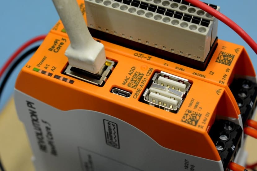
The only interfaces for direct use on the RevPi Core 3 are 2x USB, Micro HDMI and Ethernet. However, “PiBridge” connectors enable integration via RS-485 and Ethernet with up to a maximum of 10x I/O and gateway modules placed either side.
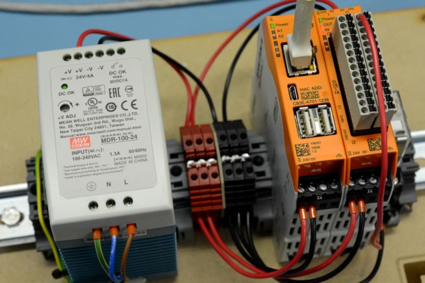
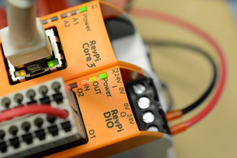
In our case, we had a single RevPi DIO — which provides 14x each digital inputs and outputs — located to the right of the Core 3. This can drive loads at up to 500mA (high-side) and although not appropriate for a relay, outputs can be configured as PWM with 40-400Hz frequency, which might be useful for controlling fan speed, for example.
There may appear to be quite a lot of cabling to the DIO for the minimal configuration here, but this is because it takes its own power supply plus separate supplies for field I/O. Which is standard practice in industrial environments and allows you to cleanly isolate potentially very noisy equipment circuits, e.g. driving motors, from more sensitive sensors and control etc.
Module configuration
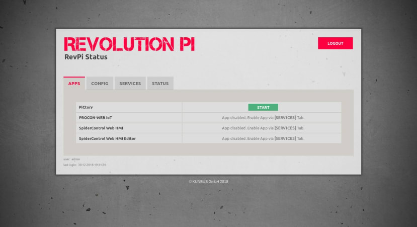
Once booted if we point a web browser at the RevPi Core IP address we are greeted by a login page, where we then enter the username admin and password that is printed on the side of the module. From here we can launch PiCtory, which is used to configure the hardware.
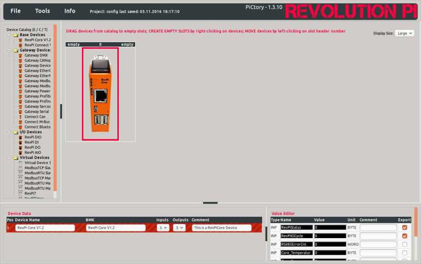
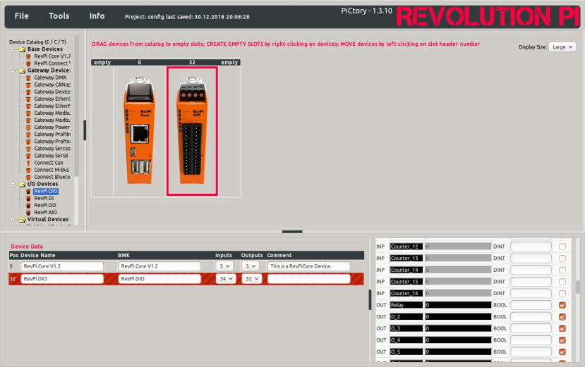
Once in PiCtory we can see our RevPi Core and to the left of this a device catalogue, from where we can select the RevPi DIO, dragging and dropping it to the right-hand side of the Core — just as it is physically installed.
We can then select the I/O module and in the bottom-right section of the web page see the inputs and outputs. Now we had the 24VDC relay wired to output 1 and we could have left this with the default label of O_1, but chose instead to rename this to “Relay”.
First test
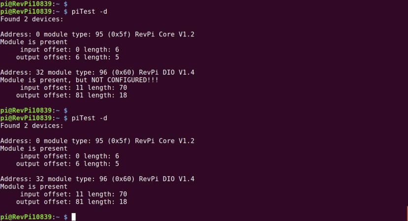
The simplest way of interacting with I/O is to log in to the RevPi Core over SSH and use the PiTest utility. Above we can see this when it is run with the device list option, both prior to the above configuration steps and afterwards.
We can also run this with options to read or write a variable. Above it is being used to first turn the relay on and then turn it off.
Process image
Now would seem a good time to talk about the process image, which reflects the state of the various configured inputs and outputs. When an input is read this is read from. When an output is written the process image is written to. At a period referred to as the cycle time and this can vary depending upon the exact number of inputs and outputs configured.
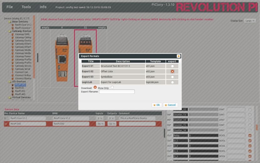
From within PiCtory we can export configuration data in a variety of different formats. For example, the IEC 61131-3 standard or, as shown below, an offset list.
RevPiStatus		 0	 //BYTE
RevPiIOCycle		 1	 //BYTE
RevPiLED		 6	 //BYTE
I_1		 11.0	 //BOOL
I_2		 11.1	 //BOOL
I_3		 11.2	 //BOOL
I_4		 11.3	 //BOOL
I_5		 11.4	 //BOOL
I_6		 11.5	 //BOOL
I_7		 11.6	 //BOOL
I_8		 11.7	 //BOOL
I_9		 11.8	 //BOOL
I_10		 11.9	 //BOOL
I_11		 11.10	 //BOOL
I_12		 11.11	 //BOOL
I_13		 11.12	 //BOOL
I_14		 11.13	 //BOOL
I_15		 11.14	 //BOOL
I_16		 11.15	 //BOOL
Relay		 81.0	 //BOOL
O_2		 81.1	 //BOOL
O_3		 81.2	 //BOOL
O_4		 81.3	 //BOOL
O_5		 81.4	 //BOOL
O_6		 81.5	 //BOOL
O_7		 81.6	 //BOOL
O_8		 81.7	 //BOOL
O_9		 81.8	 //BOOL
O_10		 81.9	 //BOOL
O_11		 81.10	 //BOOL
O_12		 81.11	 //BOOL
O_13		 81.12	 //BOOL
O_14		 81.13	 //BOOL
O_15		 81.14	 //BOOL
O_16		 81.15	 //BOOL
This gives us the variables and their data type. Here we can see that the DIO O_1 output was renamed to Relay. We can also see in red its offset and depending upon our particular application, it may be more useful to use one or the other. The offset will always map to the same physical pin, whereas a custom text label could be set on any.
Following in the great Linux/UNIX tradition the process image is simply a file, /dev/piControl0. Hence we could use any one of a vast number of programming languages and frameworks at our disposal, to open this file, seek to the appropriate offset, and then read and write.
We can also use the process image to access module status signals, such as supply voltage or temperature fault. Making it much easier to conduct remote fault diagnosis and raise the alarm when something doesn’t look quite right.
RevPiModIO
#!/usr/bin/python3

import revpimodio2
import time

revpi = revpimodio2.RevPiModIO(autorefresh=True)

revpi.io.Relay.value = True

time.sleep(2)

revpi.io.Relay.value = False

revpi.exit()
Being able to directly manipulate the process image in such an open manner is a powerful feature, but admittedly not the friendliest. Thankfully, a library called RevPiModIO, which is now at its second major release, greatly simplifies this when using the Python programming language.
Above we can see a very simple script which simply turns the relay on, pauses for 2 seconds and then turns it off. Again we are using the I/O label as configured in PiCtory, which by design must be unique across all attached modules.
The library can be installed with:
$ sudo apt-get install python3-revpimodio2Other programming options
The other available options include, with the optional runtime licence, logi.CAD3, for a classic PLC programming environment. Along with PROCON_WEB IoT, UBIDOTS, and MQTT — which of course nicely paves the way for use with Node-RED.
In fact, if you’re able to use the Python library else invest a small amount of time in writing a new library for your language of choice, integration with just about any environment should be possible.
Concluding thoughts
If you come more from a maker/Raspberry Pi background it may take a moment to get your head around the idea of a process image and not directly using GPIO, but it’s only a minor jump to make and most applications should be easily portable. What you then gain is a turnkey industrial product with CE marking, fully protected I/Os and the ability to integrate sensors and actuators with ease.
Sure, it may be possible to build something functionally equivalent so far as it needs to be, for less and using a collection of DIY high-side drivers and perfboard circuits etc. However, while this may be fun for a prototype, you might not want your home heating depending upon it, nor to have to break out the scope when you get a system crash or erroneous behaviour as a pump motor spins up!
More than this, Revolution Pi provides a highly integrated user experience, courtesy of an intuitive web interface for configuration and well thought out approach. Plus error reporting, watchdogs, and a custom Linux kernel based on the official Raspberry Pi Foundation sources, with added patching for real-time performance. There is a lot to be said for deterministic behaviour in control systems...
This post has served to only scratch the surface of the Revolution Pi platform and in future posts, we hope to take a look at programming with logi.CAD3, along with actual applications.
For more information on products search Kunbus on your local RS Components website.



Comments