EVSPIN32G4 Enables Evaluation and Prototyping of 3-phase Brushless DC Motor Control
Follow article
 Dave from DesignSpark
How do you feel about this article? Help us to provide better content for you.
Dave from DesignSpark
Thank you! Your feedback has been received.
Dave from DesignSpark
There was a problem submitting your feedback, please try again later.
Dave from DesignSpark
What do you think of this article?
Feature-packed eval board gets engineers up and running quickly with the high-performance and eminently flexible STSPIN32G4 motor control SiP.
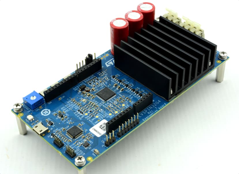
The EVSPIN32G4 (219-4217) is a demonstration board based on STMicroelectronics STSPIN32G4 system-in-package (SiP) and STL110N10F7 power MOSFETs. The STSPIN32G4 integrates a triple high-performance half-bridge gate driver with a rich set of programmable features, together with a mixed signal STM32G431 microcontroller, in a compact 9x9 mm VFQFPN package. Software support and examples for the evaluation board are provided courtesy of the STM32 Motor Control Software Development Kit (MCSDK).
STSPIN32G4
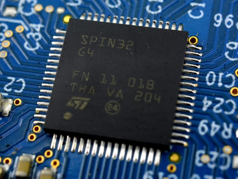
The STSPIN32G4 (219-4241) is a highly integrated and flexible motor controller for driving 3-phase brushless DC (BLDC) motors with a supply voltage from 5.5V to 75V, which helps designers to choose the most suitable driving mode and reduce PCB area and overall bill of materials (BOM).
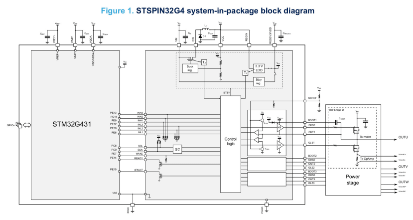
The integrated MCU (STM32G431VBx3) is based on a high-performance 32-bit ARM® Cortex®-M4 core, operating at a frequency of up to 170 MHz and featuring a single-precision floating-point unit (FPU), with a full set of digital signal processing (DSP) instructions and a memory protection unit (MPU), which enhances the application’s security. Plus numerous other key features, such as two fast 12-bit ADCs (4 Msps), four comparators, three operational amplifiers, four DAC channels, and PWM and general purpose timers. Both SWD and JTAG are available for programming and debugging, and the device has an extended temperature range of -40C to +125C.
Next let’s take a look at the standout features of the STSPIN32G4 in a little more detail.
Advanced three-phase gate drivers
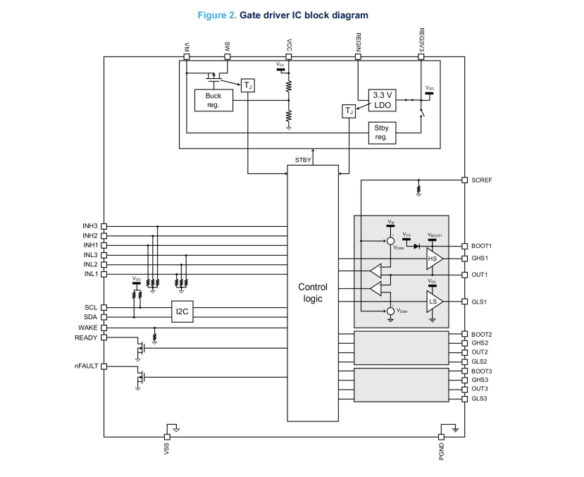
The STSPIN32G4 three-phase gate drivers feature:
- 1A sink/source current capability
- VDS monitoring of the power stage MOSFETs
- Integrated bootstrap diodes
- I2C accessible configuration and status registers for best application fit
- Cross-conduction prevention
A powerful 32-bit ARM® Cortex®-M4 MCU+FPU
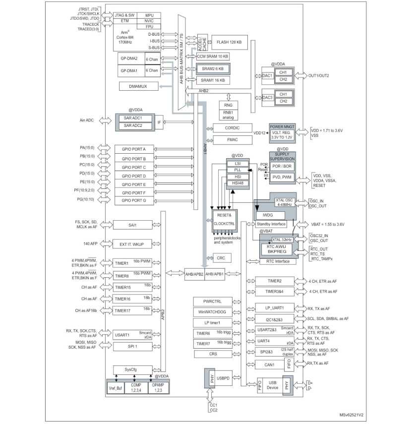
STM32G431x6/x8/xB block diagram.
The integrated high-performance STM32G431 microcontroller boasts:
- Up to 170 MHz clock frequency
- CORDIC mathematical hardware accelerator for trigonometric functions
- Filter Math Accelerator (FMAC) for CPU offload of FIR finite impulse response (FIR) and infinite impulse response (IIR) type DSP filters
- 128 kB Flash memory with proprietary code readout protection (PCROP), securable memory area, 1 kB OTP
- 32 kB SRAM memory with HW parity check
- 2 x advanced times for motor control, 16-bit with up to 6 x PWM channels
- 8 x general purpose timers
- 2 x ADCs 12-bit resolution (up to 19 channels) with 4 Msps conversion rate
- 4 x 12-bit DAC channels
- 4 x ultra-fast rail-to-rail comparators
- 3 x rail-to-rail operational amplifiers usable also in PGA mode
- Internal high precision voltage reference
- Up to 40 GPIOs
- Full set of interfaces: I2C, SPI, UART and CAN
Please note that the above block diagram is from the STM32G431RB discrete MCU product datasheet and not the STM32SPIN24 SiP documentation, hence the accessible I/O may differ.
Embedded power management, protection and more
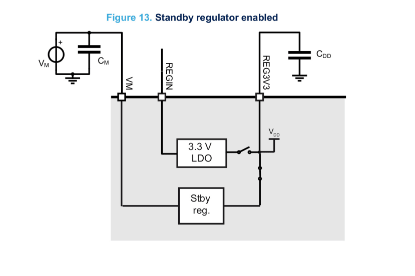
Dedicated standby regulator supplies up to 6mA current to the MCU in low consumption status.
Additional key features of the STSPIN32G4 SiP include:
- Self-supplied thanks to embedded flexible power management
- VCC buck converter up to 200 mA, with programmable output and embedded MOSFET3.3 V LDO linear regulator up to 150 mA
- Low quiescent linear regulator for MCU supply during standby
- Full set of protection features: thermal shutdown, short-circuit, overload and UVLO
- Possibility to control 2 motors simultaneously from the same MCU
- Standby mode for reduced power consumption
Typical applications
Typical applications range from home appliances such as vacuum cleaners and cleaning robots, through servo drives, e-bikes and automation robots, to drones and much more; thanks to a particularly flexible architecture which spans power management, a high performance MCU and integrated gate drivers, the STSPIN32G4 may be put to use in a great many applications.
EVSPIN32G4
The EVSPIN32G4 board (219-4217) adds the following features for the convenient evaluation and prototyping of motor control applications:
- STL110N10F7 power MOSFETs with output current up to 20Arms and protected to over-current conditions
- Configuration in three-shunt or single-shunt, supporting both sensor-less and sensor-based control algorithms
- NTC sensor for power stage monitoring
- Digital Hall sensor and quadrature encoded input
- CAN FD transceivers to enable the construction of more complex control systems
- Arduino “shield” connectors to enable interfacing with expansion boards such as such as MEMS sensors or Bluetooth and other wireless transceivers
- ST-LINK/V2 programmer that speeds up and simplifies the debugging of microcontroller firmware
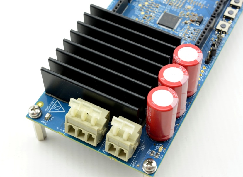
In the above image we can see the 2-pin power supply and 3-pin motor phases connectors, plus a suitably sized heatsink for the STL110N10F7 power MOSFETs which are mounted on the underside of the PCBA.
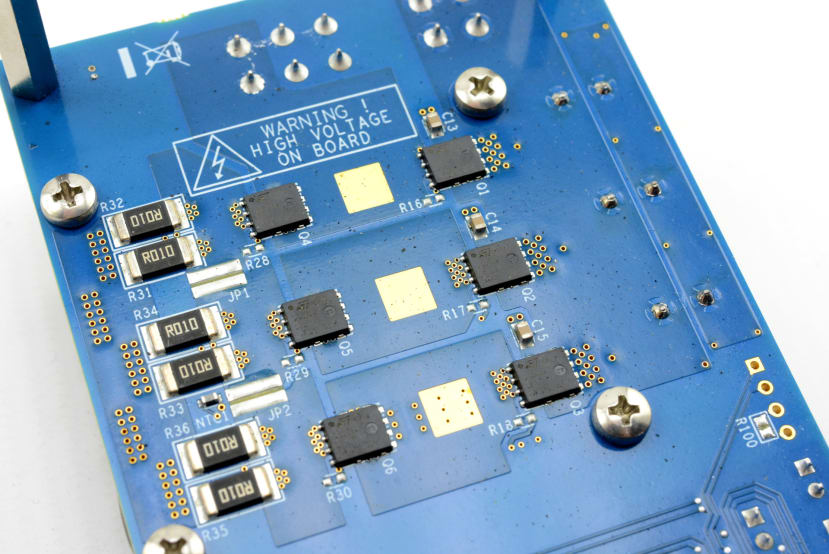
To the left of the MOSFETs are located the shunt resistors, which together with the OPAMPs integrated into the STSPIN32G4 may be used to measure current through the motor windings. The Getting Started manual provides three possible configurations: two stand-alone operational amplifiers, three stand-alone operational amplifiers, and three programmable gain amplifiers (PGAs). Details are also provided for conversion from three-shunt to single-shunt operation, and the PCB includes footprints to mount filtering capacitors on the operational amplifier feedback.
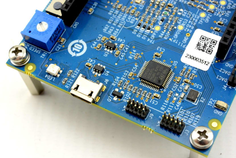
Above we can see the Micro USB connector for the integrated ST-LINK/V2 programmer. Alongside which are located headers for STSPIN32G4 JTAG/SWD, and STLINK SWD (reserved).
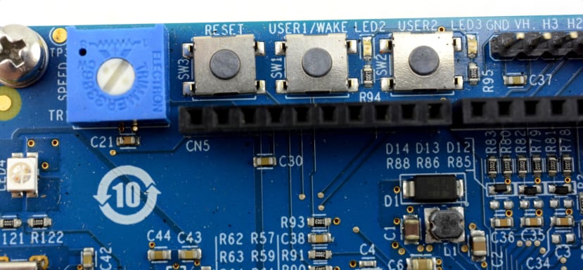
Along one side of the board we have a speed trimmer potentiometer, plus a reset push button, and two user buttons and LEDs. Just to the right of which is the Hall effect sensor / encoder connector.
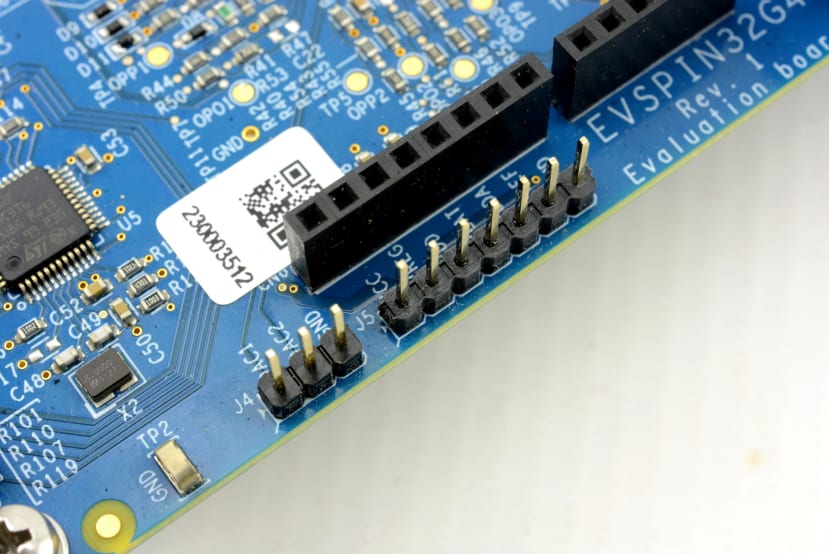
Along the opposite edge of the PCBA we have pin headers which provide access to DAC outputs and voltage monitoring. Just inside these we can see the female board-to-board connectors which form one side of the Arduino expansion footprint.
The EVSPIN32G4 board also includes additional test points which provide access to operational amplifier inputs and outputs, which should prove useful during evaluation and development.
Comprehensive details, including current measurement and temperature sensor formulae, pinouts, schematics and a full bill of materials, can be found in the Getting Started manual.
Software support
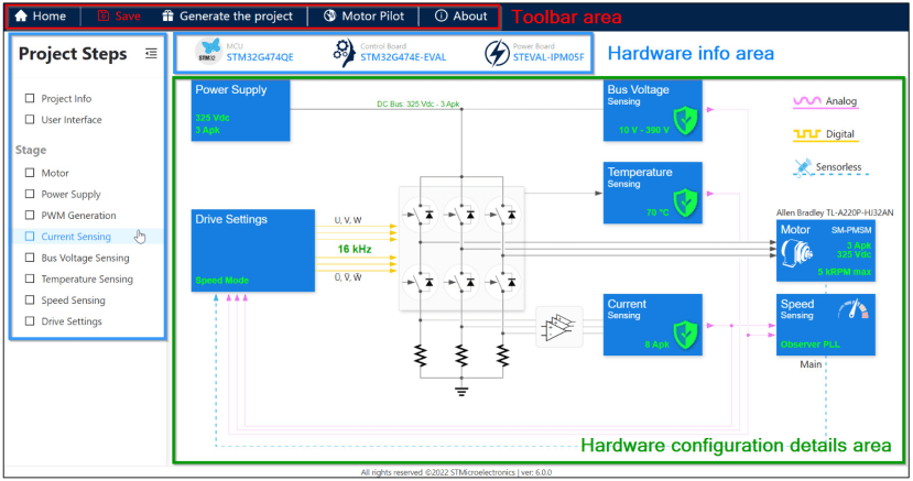
MCSDK Motor Control Workbench example screen.
Software support for the STSPIN32G4 and in turn the EVSPIN32G4 eval board, is provided courtesy of the STM32 Motor Control Software Development Kit (MCSDK). This includes the permanent magnet synchronous motor (PMSM) firmware library (FOC control) and the STM32 Motor Control Workbench (to configure the FOC firmware library parameters), with its graphical user interface (GUI).
STM32 Motor Control Workbench is a PC software that reduces the design effort and time needed for the STM32 PMSM FOC firmware configuration. The user generates a project file through the GUI, and initializes the library according to the application needs. Some algorithm variables can be monitored and changed in real-time.
Key features of the MCSDK include:
- Single/dual simultaneous field-oriented control (FOC)
- Motor profiler and one-touch tuning for a fast startup of unknown motors
- Simplified firmware architecture based on the STM32Cube HAL/LL libraries
- 1 and 3 shunt, and isolated current sensor (ICS) current reading topologies
- Speed/position sensors (encoder and Hall) and sensorless operation (state observer)
- On-the-fly startup for fans
- Speed and torque control
- Motor control algorithms implemented for specific applications, among them maximum torque per ampere (MTPA), flux weakening, feed forward, and start-on-the-fly
- Full customization and real-time communication through STM32 Motor Control Workbench PC software
A Windows computer is required for developing firmware and in addition to the MCSDK, an IDE and C compiler needs to be installed. These may be provided by the free-of-charge STM32CubeIDE, which is based on the Eclipse/CDT IDE framework and GCC toolchain. Alternatively, MCSDK may be used with a commercial IDE/toolchain, such as IAR Embedded Workbench for Arm or Keil MDK tools.
Final words
The STSPIN32G4 SiP provides an extremely integrated solution for BLDC motor control, with industry-leading flexibility thanks to a combination of a powerful and feature-packed STM32 MCU, plus configurable three-phase gate drivers. Not to mention comprehensive firmware development support through use of STM32CubeIDE and MCSDK. Rapid evaluation and prototyping meanwhile being made possible thanks to the EVSPIN32G4 board.
Comments