Evaluation Environment for Brushless DC Motors with Inductive Position Sensor IC using Renesas RA6T2
Follow article Dave from DesignSpark
How do you feel about this article? Help us to provide better content for you.
Dave from DesignSpark
Thank you! Your feedback has been received.
Dave from DesignSpark
There was a problem submitting your feedback, please try again later.
Dave from DesignSpark
What do you think of this article?
The Renesas RA6T2 Group is the second RA ASSP product targeting motor and inverter control solutions. To enable a quick check of BLDC motors with inductive position sensor IC, a GUI evaluation environment has been developed for RA6T2. Both evaluation kits used in this evaluation (Figure 1) can be purchased on the web.
- Evaluation kit MCK-RA6T2 with RA6T2, which is RA family MCU specialized for motor control: MCK-RA6T2 - (239-5705)
- Evaluation kit for IPS2200 which is an inductive position sensor IC: Evaluation Kit for IPS2200 - (250-3774)

Figure 1: Evaluation Environment for BLDC Motor with Inductive Position Sensor IC
Motor software has been developed to enable immediate use of the evaluation environment. It uses analog input information (sine and cosine signals) from inductive sensors for feedback control, allowing the evaluation of motor control using such sensors.
The features of the inductive sensor are introduced at the end of this article. In addition, refer to the table below regarding software specifications (motor rotation speed, position control range, etc.).
Table.1 Software Specification

In addition, this software includes a program that allows the user to quickly check the setup of the evaluation environment. After flashing the software onto the RA6T2 MCU, the user can turn the volume resistor mounted on the inverter board to turn the motor in sync. The evaluation environment has been successfully set up if this operation can be confirmed.
Refer to the video below for information on setting up the evaluation environment. Detailed information about this software is provided in the application note. Both the application note and the sample project can be obtained from the RA6T2 product page.

As for motor evaluation, the Renesas Motor Workbench is a free-of-charge easy-to-use GUI provided by Renesas and introduced in the video. It makes it possible to operate, monitor and vary motor variables on a GUI. Thus, the evaluation can be performed smoothly and leads to improved development efficiency because actions such as flashing and resetting the MCU are not required.
Figure 2 below showcases a snippet example of the evaluation environment. The figure is a captured image of position control operation when a position command value is given. The position, speed, and q-axis current information can be grasped in one waveform, making it easier to grasp the motor's operating status.
One example of an evaluation is shown below. The below image (Figure 2) is a captured image of the position control operation when a position command value is given. The position, speed, and q-axis current information can be grasped in one waveform, making it easier to grasp the motor's operating status.
- Green line: Position value is shown as a waveform. The position value increase as the speed is not 0, once the speed goes back to 0, the position value becomes a constant number.
- Orange line: Speed value is shown as a waveform. The speed accelerates → constant speed → decelerates
- Purple line: q-axis current value is shown as a waveform. The value is positive during acceleration and negative during Deceleration due to braking.
In addition to these motor variables, other variables that are useful for evaluation are prepared in the software. If you are interested, refer to the following application note.

Figure 2: Captured image of position control operation when a position command value is given
From here, the inductive position sensor will be briefly introduced. The inductive position sensor is a non-contact sensor that uses electromagnetic induction to detect the position of the motor. The sensing element uses a coil pattern layout on a printed circuit board as shown in figure 3, and the position of the motor can be detected when a metal plate passes over this sensing element. This position information is output as sine and cosine wave data via the inductive position sensor IC.

Figure 3: Coil pattern layout on board and motor connection image
The advantages of using this inductive position sensor include its functionality.
The sensing element used in the inductive position sensor can be layout with the same number of coil patterns as the pole pairs of the motor to be used (left side of figure 4), so it can be adapted to the motor with various pole pairs. The coil substrate for the inductive position sensor can be mounted at the end or base of the shaft, providing high flexibility in designing motor machinery (right side of figure 4).
Furthermore, the inductive position sensor can be adapted to a variety of motors, but to improve positional accuracy, the coil substrate must be created to match the motor used.
Renesas provides a support tool (Inductive Coil Design Tool Software) and 80 reference designs for developing this coil board. Do take advantage of these tools when developing your board.
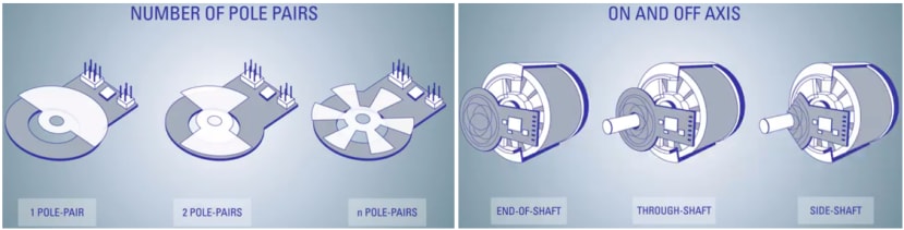
Figure 4: Inductive position sensor pole logarithm and layout example
The second advantage is environmental durability.
Since no magnets are used in the sensing element, it is highly resistant to surrounding magnetic fields and at the same time lightweight. In addition, the non-contact method provides high resistance to dust and dirt.
The last advantage is the low cost.
In general, it is easier to lower the total cost of inductive position sensors compared to optical or magnetic encoders due to the number of elements and components used. The optical encoder sensor is inherently more expensive, while the magnetic encoder increased cost comes from the need for magnetic shielding, etc.

Figure 5 Comparison of cost for the three position sensors
To summarize, inductive position sensors can optimize position accuracy by designing the coil substrate to match the motor used and have high environmental resistance along with the reduced weight of motor equipment. In addition, a motor control system with position sensing function can be realized at a lower cost compared to other position sensors. As a result, the use of this sensor is expanding in applications that require high-precision position detection in harsh environments, such as industrial motors, robots,
Finally, the product page for RA6T2, an MCU for motor control, includes a wealth of application notes and sample projects for motor control with encoder IF, sensor-less control, BLDC motor control with an inductive position sensor, and more. It can be applied to a wide variety of motor control devices.
Experience superior performance in motor control with the RA6T2 MCU and evaluation environment that allows for immediate evaluation and medical equipment.
WEB:
Comments