DesignSpark PCB - Simply create multigate components
Follow article
 Dave from DesignSpark
How do you feel about this article? Help us to provide better content for you.
Dave from DesignSpark
Thank you! Your feedback has been received.
Dave from DesignSpark
There was a problem submitting your feedback, please try again later.
Dave from DesignSpark
What do you think of this article?
Note: to use the below features, you will need DesignSpark PCB with an Engineer subscription.
DSPCB provides a simple way to create multi-gate components i.e. the component schematic symbol consists of separate symbols for ease of placing in any location on your schematic design.
The feature in DSPCB Engineer that makes this easy is the Tabs at the bottom of the screen which provides quick access.
Open a component to edit and explore!
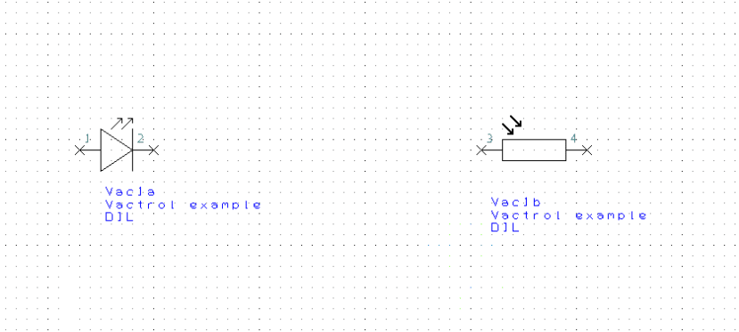
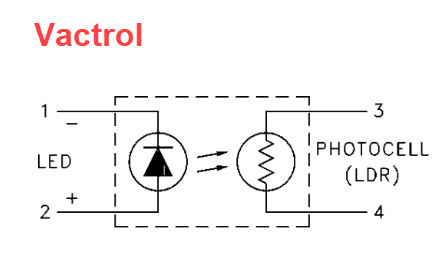
For this example, a user asked how to create a "Vactrol" symbol as shown in the top image. This is a LED coupled to a light-dependent resistor (LDR) contained in a light-tight package.
The requirement was to produce a schematic symbol with the LED and LDR as separate 'gates'.
From the Library Manager select the Component tab and then <New Item>
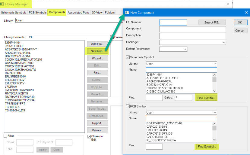
Select the PCB Symbol and also the Schematic Symbol for the first gate and the number of gates using this symbol, which is "1" for this example.
Important. You will add second (and subsequent) Schematic Symbols at a later step.
Complete the component details at the top of the window.
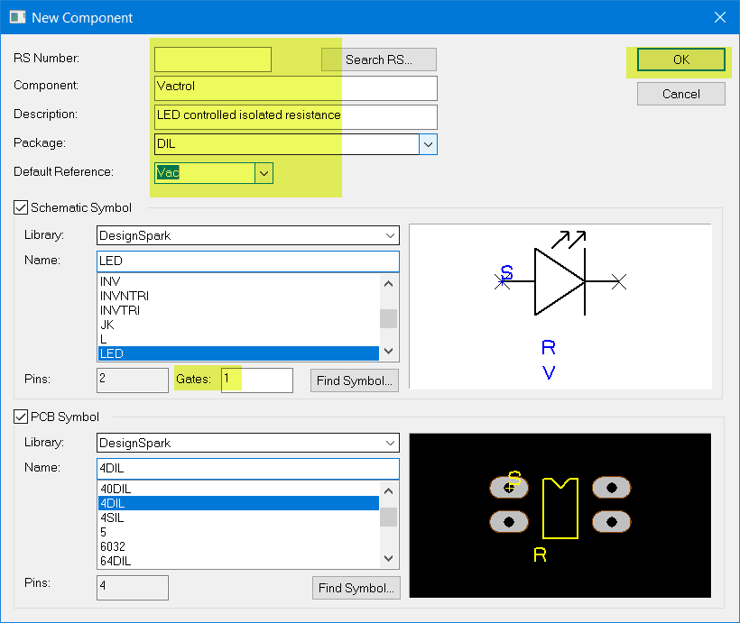
When you click <OK> the following window opens.
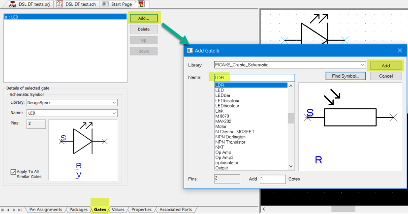
Select the "Gates" tab at the bottom of the screen and you will see the current schematic symbol present.
Click <Add...> and in the new "Add Gate b" window you can now select as before a schematic symbol and the number of gates required.
Click <Add> when your selection is complete.
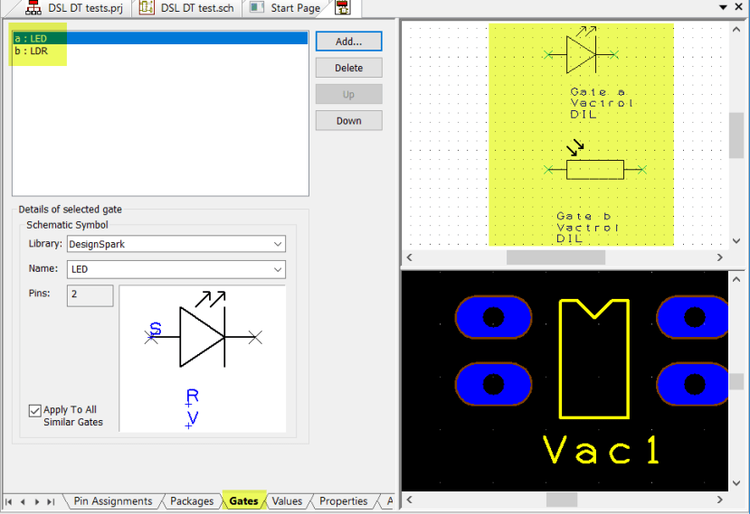
We now have the component with the required schematic symbols. You can repeat this step to add further symbols as required.
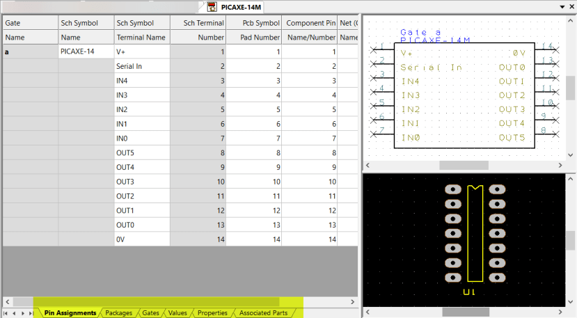
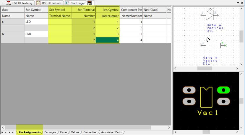
Now assign the pin number mapping between the Schematic Symbol and the footprint pads.
Select the "Pin Assignments" tab and complete the table as required, you can also add terminal names to assist you while wiring the schematic
From the menu bar save the new component to the required library and it's ready to use in your design.