DesignSpark Mechanical | How to align & mate components
Follow article
 Dave from DesignSpark
How do you feel about this article? Help us to provide better content for you.
Dave from DesignSpark
Thank you! Your feedback has been received.
Dave from DesignSpark
There was a problem submitting your feedback, please try again later.
Dave from DesignSpark
What do you think of this article?
It's pretty common when creating a mechanical design to use off-the-shelf components. After all, we aren't trying to re-invent the wheel. When we shop for components, it's super easy to download a STEP file and drop it into our design.
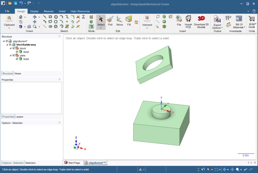
This brings us to the need to be able to properly position the imported component in our design. This tutorial shows how to align and mate a component with respect to another component in our design. We will use the Move tool. Here I'll use a simple example where I am adding a square plate to my design. Initially, it's not positioned where I want it. I want to move it so that it
- sits on the top face of the block
- with its hole located concentric to the round post on the top of the block
- and with its sides parallel with the sides of the block.
I will try to use what I consider to be Best Practices in this example.
- My solids are each located within their own component.
- My components are placed in an assembly component which is located under the top assembly.
Now, on to the job at hand. Select the plate component and click Move.
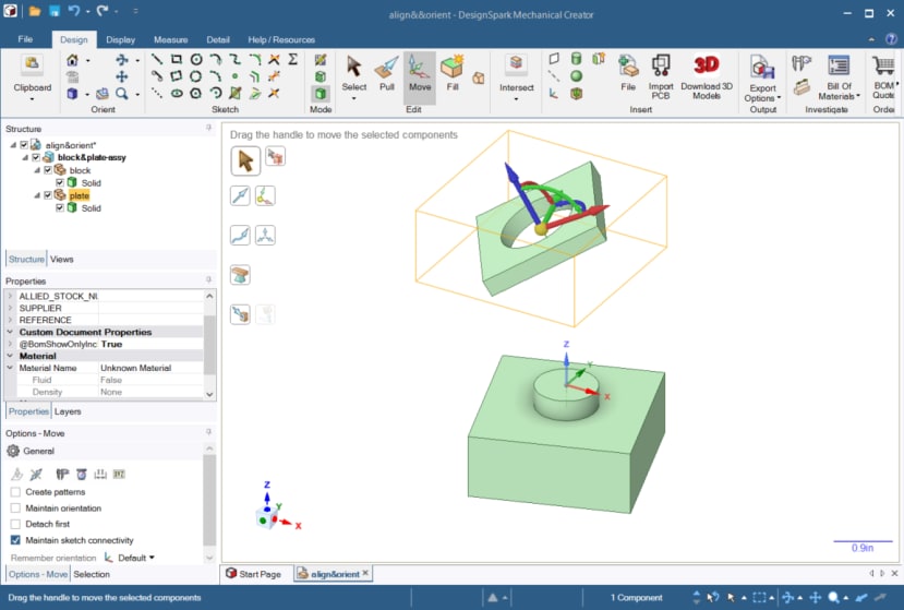
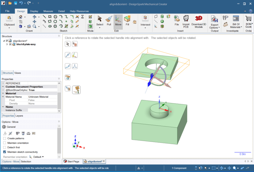
Next, click on the blue translation arrow. This causes the blue translation arrow to be selected. (The others get greyed out.) It also causes the Orient to Object tool guide to become enabled. (It was previously greyed out.) Click on the Orient to Object tool guide.
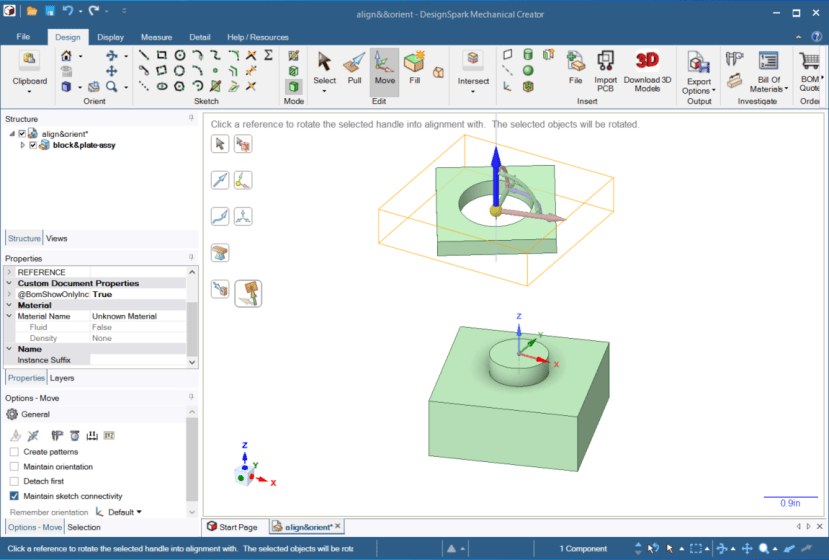
Next, click on the top face of the block. This will cause the plate to move so that the direction of its blue translation arrow will become parallel to the surface normal vector of the face clicked on the block. This just happens to be the Z direction (by coincidence).
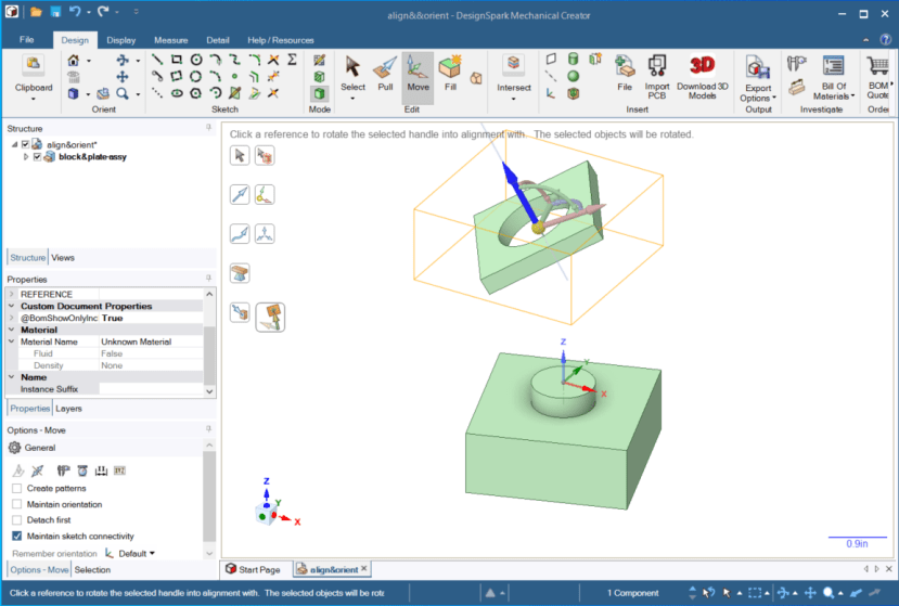
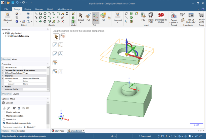
Next, click on the Anchor tool guide then click on the front face of the plate. The blue translation arrow is still selected and that's what we want. The blue translation arrow is pointed along the surface normal of the plate's front face.

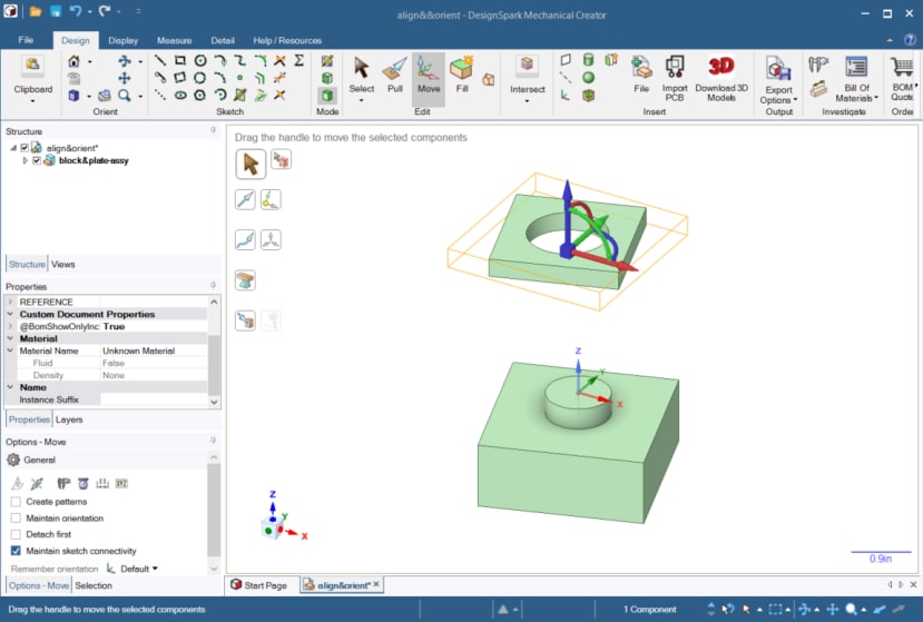
Next, click on the Orient to Object tool guide, then click on the front face of the block. As before, this causes the plate to move so that the direction of its blue translation arrow will become parallel to the surface normal vector of the face clicked on the block.
OK, we have the plate oriented correctly. We just need to move it so that the centre of the bottom of the hole is coincident with the centre of the base of the post on the block. For this we will use Move again, but this time with the Up To tool guide. Right now, our Move tool has some of its DOF greyed out. We need a fresh move tool, with all DOF enabled. Click Select then click on Move again to get a fresh Move tool.
Next, click on the Anchor tool guide to move the anchor to the centre of the bottom of the hole in the plate.
The final step is to click on the Up To tool guide and then click on the circle at the base of the post.
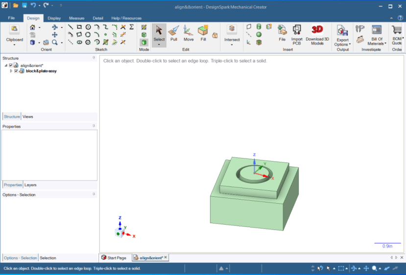
That's it! We're done. Click Select to exit the Move operation.
Here is a 1-minute video showing the mate & align process.
Now you can import components and assemblies into your design and put them right where you want them.
Comments