Getting Started with Xilinx Zynq, All Programmable System-On-Chip (SoC)
Follow article Dave from DesignSpark
How do you feel about this article? Help us to provide better content for you.
Dave from DesignSpark
Thank you! Your feedback has been received.
Dave from DesignSpark
There was a problem submitting your feedback, please try again later.
Dave from DesignSpark
What do you think of this article?
What is FPGA
Xilinx is famous for making Field Programmable Device Gate Array (FPGA), which are based around a matrix of configurable logic blocks (CLBs) connected via programmable interconnects. According to the article "Advantages of FPGA" in Control Engineering Europe, speeds can be extremely fast, and multiple control loops can run on a single FPGA device at different rates. FPGAs can also be reprogrammed to a desired application or functionality requirement after manufacturing, making them highly popular among future and professional engineers. Many of whom apply this technology to machine learning, wireless communication, embedded vision and cloud computing applications.
What is ZYNQ
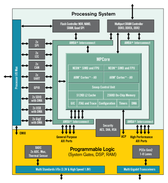
Xilinx Zynq®-7000 All Programmable SoC (AP SoC) family integrates the software programmability of an ARM®-based processor with the hardware programmability of an FPGA. This technology enables key analytics and hardware acceleration while integrating CPU, DSP, ASSP, and mixed signal functionality on a single device.
Installing Vivado, SDK & Board Support Files
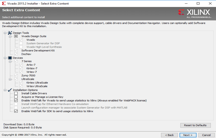
Before creating the digital / systems design you will need to install the Xilinx Vivado Design Suite. The Xilinx Vivado Webpack version is free, with guidelines provided on the Digilent Wiki to help you get Vivado up and running in no time. When downloading Vivado, make sure you check the box labeled "Software Development Kit" under Design Tools to install the SDK. In case you forget to do so, you can always go back to the installer and install the "Software Development Kit".
Once you have downloaded and installed Vivado, you will need to put the ZYBO board file, which defines different interfaces and peripherals on the board, into the local Xilinx Vivado folder. This will allow you to build the IP and SDK successfully later. Digilent provides a how-to guide for this process at https://reference.digilentinc.com/reference/software/vivado/board-files?redirect=1.
Note: In the Vivado board files installation guideline, you will be asked to put the master file (board_files) into your local folder. However, I recommend that you only copy the individual board file (i.e. once you have downloaded the vivado board files, go to vivado-boards-master\new\board_files and only copy the "zybo folder"). Otherwise, you may get some non-necessary error during the design.
Create Project
I will now use the Digilent ZYBO and follow their getting started guide to create a simple Hello World project.
Project Overview
In this project you will learn how to control the on-board LEDs (LD0-LD3) with 4 on-board switches (SW0-SW3). When you push four different on-board buttons (BTN0-BTN3), you can see various messages from the computer terminal.
Design Flow
-
Open Vivado and select Zybo board
-
Create an new Vivado Project
-
Create empty block design workspace inside the new project
-
Add required IP blocks using the IP integrator tool and build Hardware Design
-
Validate and save block design
-
Create HDL system wrapper
-
Run design Synthesis and Implementation
-
Generate Bit File
-
Export Hardware Design including the generated bit stream file to SDK tool
-
Launch SDK
Hardware Design Overview
You can follow Step 2 to Step 6 from the getting started guide to create the hardware design. Here are some remarks.
- The Run Block Automation dialog box allows you to provide input about basic features that the microprocessor system needs.
- From "3.4) Double-click on new axi_gpio_0 core that was just added to bring up the customizing window. Under the IP Configuration tab check the Enable Dual Channel box. Click OK.", you will create two inputs - SW and BTN. Each axi_gpio core supports 32 bits single or dual GPIO channel(s). In this project, we only need 4 bits in each channel. You can find the details at AXI GPIO Guide.
- From "3.5) Add another GPIO core by repeating step 3.3 but do not enable dual channel.", you will create one output - LED.
- The Run Connection Automation assists you in hooking interfaces and/or ports to external I/O ports.
- By default, one of the UART interfaces (UART1) has been populated in the ZYNQ IP. Reference: http://blog.dev-flow.com/en/8-first-use-of-the-zynq-7000-processor-system-on-a-zynq/.

Software Design Overview
You can follow Step 7 to Step 10 from the getting started guide to create the software design. Here are some remarks.
When you open "helloworld.c" under the "src" folder (refer to step 9.4 in the getting started guide), you can look at the details of pre-defined fuctions and libraries in the user interface by the following methods
Highlight functions / libraries
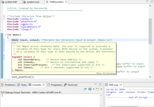
Right click the predefined function / library and open new tab to see declaration

The source codes with comments are below
/*****************************************************
Getting Started Guide for Zybo

This demo displays the status of the switches on the
LEDs and prints a message to the serial communication
when a button is pressed.

Terminal Settings:
   -Baud: 115200
   -Data bits: 8
   -Parity: no
   -Stop bits: 1

1/6/14: Created by MarshallW
****************************************************/

/*include libraries from Xilinx*/
#include <stdio.h>
#include "platform.h"
#include <xgpio.h>
#include "xparameters.h"
#include "sleep.h"

int main()
{
   XGpio input, output; /*Declare two structure input & output. XGpio is*/
   int button_data = 0; /*Declare & Define initial button value*/
   int switch_data = 0; /*Declare & Define initial switch value*/

   /*Initialize the XGpio instance provided by the caller based on the given DeviceID.*/

   XGpio_Initialize(&input, XPAR_AXI_GPIO_0_DEVICE_ID);	/*We define AXI_GPIO_0 as inputs - BTN & SW*/
   XGpio_Initialize(&output, XPAR_AXI_GPIO_1_DEVICE_ID);/*We define AXI_GPIO_1 as inputs - LED*/

   XGpio_SetDataDirection(&input, 1, 0xF);			/*set first channel of input tristate buffer to input*/
   XGpio_SetDataDirection(&input, 2, 0xF);			/*set second channel of input tristate buffer to input*/

   XGpio_SetDataDirection(&output, 1, 0x0);		/*set only channel of output tristate buffer to output*/

   init_platform(); /*Initialize the platform hardware resources*/

   /*Indefinite loop - running forever*/
   while(1){
      switch_data = XGpio_DiscreteRead(&input, 2);	/*Read the switch (SW) value*/

      XGpio_DiscreteWrite(&output, 1, switch_data);	/*Write the switch (SW) value to LED (LD)*/

      button_data = XGpio_DiscreteRead(&input, 1);	/*Read the button (BTN) value*/

      /*Set up if-else-if statement to print message in the
       *UART terminal. This depends on whether one or
       * more buttons are pressed
       */

      if(button_data == 0x0){} /*If no button is pressed, do nothing*/

      /*If button value is binary 0001 (decimal 1), button 0 (BTN0) is pressed. Use pre-defined function Xil-printf
       * to print the message in the terminal
       */
      else if(button_data == 0x1)
         xil_printf("button 0 pressed\n\r");

      /*If button value is "binary 0010 (decimal 2)", button 1 (BTN1) is pressed. Use pre-defined function Xil-printf
       *to print the message in the terminal
       */

      else if(button_data == 0x2)
         xil_printf("button 1 pressed\n\r");

      /*If button value is "binary 0100 (decimal 4)", button 2 (BTN2) is pressed. Use pre-defined function Xil-printf
       *to print the message in the terminal
       */

      else if(button_data == 0x4)
         xil_printf("button 2 pressed\n\r");

      /*If button value is "binary 1000 (decimal 8)", button 3 (BTN3) is pressed. Use pre-defined function Xil-printf
       *to print the message in the terminal
       */

      else if(button_data == 0x8)
         xil_printf("button 3 pressed\n\r");

      else
         xil_printf("multiple buttons pressed\n\r"); /*All other values, print "multiple buttons pressed*/

      usleep(200000);			/*Delay 200000us*/

   }
   cleanup_platform(); /*Clean up all caches*/
   return 0;

}
Run Project
You can follow Step 11 to run the project. After you program the FPGA and build the application successfully, you can see the following
- Try playing around with the 4 switches (labeled SW0-SW3). Doing so should light its respective LED.
- Over the serial port, pressing each button (labeled BTN0-BTN3) will produce the message “button x pressed”.
