Autonomous System Development Platform
Follow articleHow do you feel about this article? Help us to provide better content for you.
Thank you! Your feedback has been received.
There was a problem submitting your feedback, please try again later.
What do you think of this article?
My interest in robotics was first sparked when I was working in the defence industry, I noted the huge investment being committed to the development of what we were calling “autonomous systems” which ranged in application hugely from sea-floor mapping, oceanography and even mine-sweeping to complement the evolution of the naval sector adopting high-tech, low profile vessels with smaller operating crews. Of course, now that I am working in the automotive industry, I have found that more people are aware of this progress in the context of self-driving technologies and the buzz generated from big technology firms as they race to perfect their designs for the public.
With this technology being a driving force behind contemporary robotics, I was inspired to build a modular, maker-friendly platform for developing autonomous systems of my own design. The build process has been documented below.
Parts list:
- 4x 250mm solid plastic and rubber wheels
- 4x 8mm shaft-couplings with grub-screws
- 4x 12v DC gear-motors
- 4-core multi-strand cable
- 2x IP68 cable glands
- General purpose shrink-wrap
- M8 stud-bar
- M8 plain hex-nuts (can use nyloc)
- M8 screws
- M8 penny washers
- Gewiss GW-44-207 IP56 enclosure
- 1500mAh Li-Ion battery
- Custom 3D printed battery holder with M4x30 holding screw and nut
- Molex connector assemblies
- Single core cable
- M4 self-tapping screws
- Custom PCB
- 3mm aluminium plate
- SPST toggle switch
It is worth noting that I have been thorough with the design of this project which has involved a lot of CAD work in the form of DesignSpark’s PCB and Mechanical software.
Chassis
The aluminium chassis side-panels are used to mount the motors and electronics enclosure while also fixing the stud bar that completes the mechanical superstructure. It was originally fabricated by hand out of rusty scrap steel which worked excellently but was a bit rough so I decided to CAD and cut the chassis panels again using a proper CNC machine and lightweight aluminium. The drawing can be seen below.
DesignSpark Mechanical
Motors
Each of the main driving motors is mounted to the chassis side-panels with four M4 screws respectively, the chosen motors have a high gear-ratio for increasing the torque needed to turn the large wheels attached to each rotor. The four-wheel drive effect of the motors gives the robot excellent traction. So far I have driven it up a 45-degree wooden ramp with no slip and flipped it over by gripping a vertical brick wall to test its inverted operation.
The robot was not designed to drive like a conventional car with complex steering linkages, rather it was designed to handle rough terrain more aggressively like a tank using its four-wheel drive to turn on the spot. Please note the track to wheel-base ratio does not aim to use to the golden ratio (1:1.6) like in car design but rather uses a 1:1 ratio for perfect torque vectoring when skid-steering.
Wheels
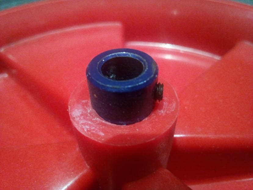
The large solid plastic and rubber wheels chosen make the platform excellent in difficult terrain with a good mix a traction and ground clearance. The chassis of the robot is actually impossible to hit with a wide, flat surface because of the protection from the wheels. The wheels are attached to the motor shafts with the help of an 8mm shaft coupling super-glued half-way into the hollow axle of the wheel, leaving a grub-screw exposed to attach the wheel to the motor shaft.
Enclosure
The chosen enclosure is IP rated for any splashes or rain that it might encounter in its operating environment. It is attached to the aluminium chassis with machined holes for two M8 bolts, nuts and washers either side, which adds strength to the overall structure. The enclosure has other machined holes for the IP rated cables glands on the front and back of the enclosure and another for the on/off toggle switch at the back.
PCB and control system design
The default system was designed to run as an ROV or “remote operated vehicle” with the potential for basic telemetry. It can be augmented with the extended I/O expected from a lot of maker development-kits, allowing for quick and easy expansion into a fully autonomous system.
The resulting hardware architecture behind this design-mentality included the use of an enablable Bluetooth transceiver for smart-phone control and telemetry, an Atmel ATMEGA328P-PU IC with Arduino bootloader for easy UART programming, as well as Analogue, I2C and SPI interfacing terminals for connecting many ICs, shields and development-boards including the Raspberry Pi.
Actuator control was enabled through a pair of MOSFET H-bridge circuits controlled from the PMW compatible digital pins of the ATMEGA. The power supply to the circuit was a 1500mAh 11.1v Li-Ion battery but the microcontroller logic supply was regulated down to 5v which needed to be buffered back up to 11.1v to drive the power to the motors. Caution was taken by adding extra solder to the copper tracks of the PCB to minimise I2R losses and excess heat produced from any current.
DesignSpark PCB
The battery and PCB were connected with single-core cable and turned on/off with a simple toggle switch in series. Using some Molex connector assemblies, I designed the battery to be easily removable for charging without having to unscrew any terminal blocks on the PCB. Four-core multi-strand cable was used to connect the motors at the front and back, with the H-bridges controlling the left and right motor channels respectively.
I sourced the PCB from Eurocircuits using their affordable “naked-proto” online service.
3D printed battery mount
One problem I faced with the precursor design was the battery rattling when the platform was driving around. I thought I would try and restrain the battery with an easily operable internal mount, thus making the design more rugged. Using DesignSpark Mechanical I was able to create a design quickly to then export for printing out of PLA. Using this design, I could mount my battery firmly using M4 screws and not worry about it hitting the PCB components anymore.
DesignSpark Mechanical
Smart-phone app
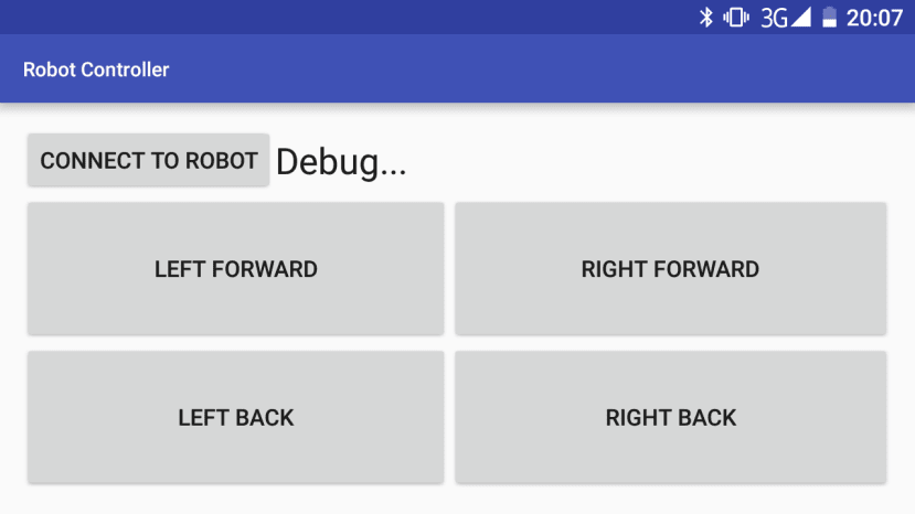
The use of a Bluetooth transceiver on the control system enabled basic IOT style networking and direct control of platform mechatronic elements. The most exciting application of this is the remote operation mode executed through a very basic Android smart-phone app used to control the left and right wheel directions. The novelty of Bluetooth control is that it does not need a stand-alone controller but rather a common smart-phone or tablet which use common ISM multiple-access frequency bands. However, this also means that the signal range is short and subsequent design iterations of the platform will necessitate an improved radio system and a more powerful base-station for extended missions.
Video
Conclusion
This project was an evolution of what I started as part of my undergraduate dissertation with the platform having grown alongside my interest in autonomous robotics and driverless technology. Having been constantly inspired by the wide range of impressive tasks these machines are capable of, I would love to be able to scale what I have achieved so far in all-terrain autonomous development platforms onto the larger world-stage such as the Dakar rally and I will certainly keep developing these ideas as this ambition grows.


Comments