A look into the Electronics of a Hyperloop Pod
Follow article Dave from DesignSpark
How do you feel about this article? Help us to provide better content for you.
Dave from DesignSpark
Thank you! Your feedback has been received.
Dave from DesignSpark
There was a problem submitting your feedback, please try again later.
Dave from DesignSpark
What do you think of this article?
Introduction
The University of Edinburgh Hyperloop Team (HYPED) is a student led, engineering society that builds a prototype hyperloop pod, from scratch, every year. We take part in a hyperloop competition in the summer called European Hyperloop Week (EHW), where we present our work, compete against other student teams from around the world, and attempt to run our respective pods.
Well, what even is Hyperloop? Hyperloop was popularised by Elon Musk in 2013 and represents the next evolution in public rail transportation. It is essentially a train in a vacuum tube which uses a Linear Induction Motor (LIM) for contactless propulsion and electro-magnetic suspension to levitate, greatly reducing friction. Predicted to reach speeds beyond 500km/h; trips like Edinburgh – London could be reduced to less than 40 minutes.

HYPED is the most successful hyperloop team in the UK, regularly receiving nominations across sub-teams at EHW. We are also responsible for the UK's first pod run, which was achieved during testing, last Summer in 2023.
This article will focus on the control hardware required to make a successful pod and will cover protocol and board selection, as well as the PCBs that have to be designed.
For more information about HYPED, please visit https://www.hyp-ed.com/.
The Role of Control
As you might imagine designing and implementing a safe and reliable control network to interface between around 40 sensors, over 10 controllers as well as the pneumatics and high-power systems can be quite a challenge. In addition, the system must operate at high speed, relaying critical information back to the “Base Station”. This involves selecting the appropriate communication protocols and controllers for the various requirements.
The following protocols are used:
- I2C, for when many sensors need to be on the same bus
- SPI, for high-speed applications
- CAN, communicating between microcontrollers
- MQTT, for communicating between Linux controllers and the base station wirelessly
Pod Ness 23/24 - Lessons from last year
Last year’s pod, “Pod Ness”, was a first for the society in many ways. We came the closest we’ve ever come to a fully working prototype by: Completing a test run across a short piece of our track, successfully designing and manufacturing more than 30 PCBs as well as designing, simulating and hand winding our own linear induction motor.
However, we also made many mistakes across multiple sub-teams. Here we’ll be focusing on the main troubles experienced in the Electronics sub-team.
Before getting stuck in, it’s worth mentioning that our hardware architecture consisted of 2 BeagleBone Blacks (BBB) (125-2411) and a singular Raspberry Pi 4B (182-2096) . The BeagleBones were in charge of all the sensors and communications, while the Raspberry Pi handled the networking with the base station and between the controllers themselves.
BEAGLEBONES
BeagleBones are essentially slightly less powerful Raspberry Pis that make up for their slightly lacking performance with an impressive 92 GPIO pins (52 more than the RPi) and some expanded I/O, including native CAN, which is useful for a vehicle with various sensors across multiple different protocols.

On paper, this seems like an excellent compromise. However, in reality, this is not quite the case. We ran into numerous problems daily, which significantly slowed down sub-team integration and testing. It turns out that our ageing BeagleBones have many quirks and features that we hadn’t discovered until we came close to finalising our pod such as:
- Randomly rebooting during use, forcing us to restart whichever test or run we were in the middle of
- Occasionally booting into read-only mode, making it impossible to flash any new code onto the board – again requiring a reboot
- General Inconsistencies such as protocols working much less reliably than when using Raspberry Pis and refusing to boot while sensors were connected
So, this was a bit of an easy fix. Unsurprisingly, this year’s control system does not make use of our beloved BeagleBones.
PS: Fun Fact, Plugging in a BBB into your computer over USB while power is plugged into the 5V barrel jack will cause the BBB to draw double the current it needs causing it to overheat (genius).
PCBS
We designed 12 unique PCBs, resulting in almost 40 manufactured PCBs on the pod. All these PCBs worked as intended but the lack of communication between design teams showed itself through the lack of standard connectors or visual consistency. This resulted in many circuits that worked and looked nice individually, but when brought together it was very clear that they had been designed by around 10 different engineers.

ARCHITECTURE
Last year it was decided that it would be easier if all the controllers were in the same box. This, combined with the lack of standardisation between connectors made wiring the 30+ PCBs across the 2m long pod a massive headache.

Poddington 23/24 – Our Current Design
This year we are starting to move away from Linux controllers (such as the BBB) in favour of more microcontrollers. We’re making use of 4 Raspberry Pi 4Bs (the Pi 5 came out too late to be included in the design) and 9 STM32 Nucleo Boards. If you’re not familiar with Nucleo Boards, think of them as powerful Arduinos with the ability to communicate over pretty much any communication protocol you can think of. We’re using them to replace the CAN functionality that the BBBs provided last year as well as various other tasks.
Raspberry Pi 4Bs
The role of our Pis in this design are as follows:
- Interface with almost all the sensors across I2C, SPI and GPIO
- Control the pneumatics through solenoids
- Control high-power SSRs in the junction box
- Networking between Pis and with the base station
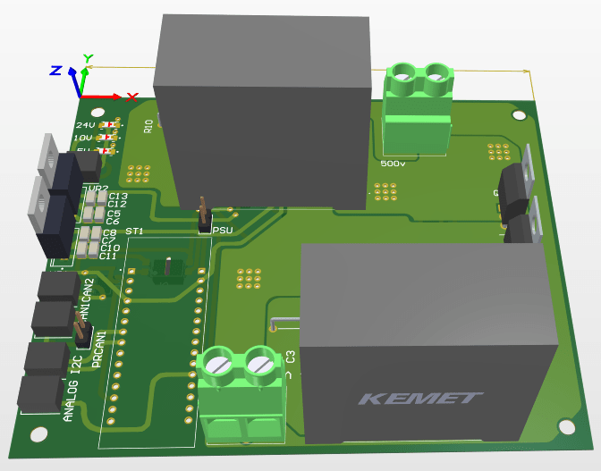
3 of the 4 Pis are located at the front of the pod. A double hat PCB for 2 of the front Pis has been designed and will be manufactured and populated shortly:

The last Pi is placed at the back and greatly simplifies wiring by dealing with all the sensors and switches present at the back of the pod:

STM32 Nucleo Boards
STM32 Nucleo Boards satisfy the following requirements for us:
- Masters on our CANBus
- Controllers in our 6 levitation modules
- Used as the controller for our custom motor inverter
- Used for our regenerative braking circuit
We made use of 6 of the tiny Nucleo-L432KC (143-8574) as our levitation controllers. They operate a PID loop using the height of the pod as input and output a high-frequency PWM signal to the levitation modules. One of our test modules for levitation can be seen below:
The remaining 3 Nucleo Boards are the powerful Nucleo-F767ZI boards (123-1052) , which have a much bigger footprint, but the additional computing power allows us to use them for higher-performance applications requiring many pins and fast response times.
We use one simply for communicating between the CANBus and the Ethernet switch. Another for our custom LIM inverter, and the last is controlling our regenerative braking system.
Base Station
In previous years the Base Station has consisted of a software team member sitting on the track with a MacBook connected to the Pod’s telecommunication system. Using NASA’s openMCT software we’ve created a beautiful Graphical User Interface (GUI) for controlling and monitoring the operation of the pod:
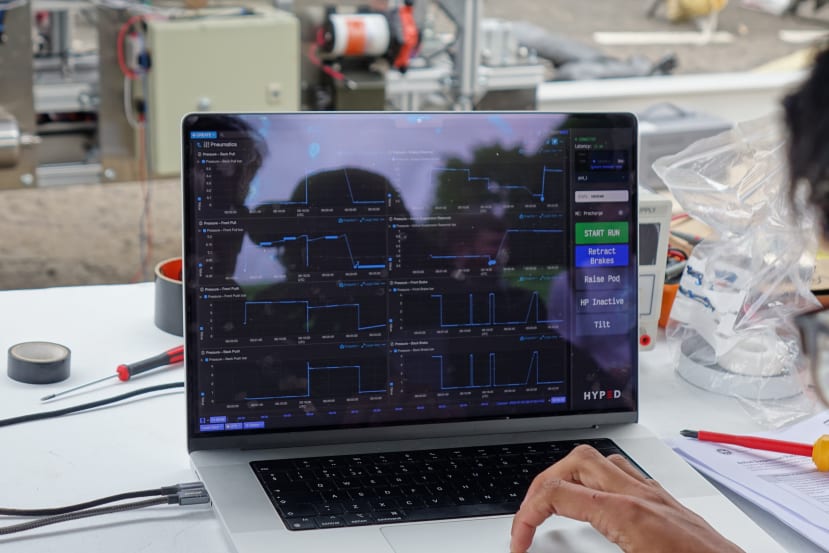
This year we’ve gone beyond this and created a web app which anyone can open and track how the pods doing. You can visit anytime at https://app.hyp-ed.com/ (currently randomised data).
Looking Forward
After summarising our designs so far, I hope I've given a good idea of the impressive progress we've managed to make as a part-time student society. In the next few weeks, we plan to finish all our PCB designs and start manufacturing and soldering them. Following this, we'll start integrating with the mechanical and software sub-teams and hopefully end up with a working, moving, floating Pod!