A First Look at the Renesas Target Board for RX671
Follow article
 Dave from DesignSpark
How do you feel about this article? Help us to provide better content for you.
Dave from DesignSpark
Thank you! Your feedback has been received.
Dave from DesignSpark
There was a problem submitting your feedback, please try again later.
Dave from DesignSpark
What do you think of this article?

Enabling evaluation and prototyping with Renesas 32-bit MCU for fast real-time control and contactless HMI, with features including cap touch, serial sound interface and encryption.
The Renesas Target Board for RX671 (229-8248) provides an entry point to evaluation and prototyping with the MCU, with the inclusion of an emulator circuit meaning that no other hardware tools are required in order to start developing and debugging applications. Supported also by the powerful e2 studio integrated development environment (IDE), packed with features such as Smart Configurator, Firmware Integration Technology (FIT) and GDB hardware debugger.
Before we get on to the Target Board itself, let’s first take a closer look at the RX671 MCU group.
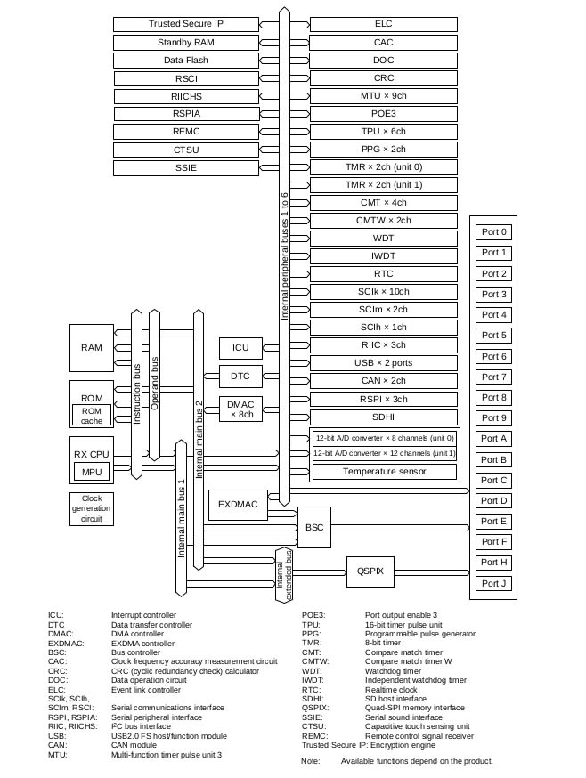
RX671

RX671 group MCUs build upon a Renesas RXv3 core running at 120MHz, integrating HMI functions for contactless operation by proximity switches and voice recognition.
The main features of the RX671 include:
- 120MHz RXv3 core (707 CoreMark, 48.8 CoreMark/mA), double-precision FPU, and register bank save function that speeds up interrupt response
- 2MB flash memory (60MHz read access, dual bank function), 384KB SRAM
- Capacitive touch sensing unit and serial sound interface
- SD host interface, USB 2.0 full speed, CAN 2ch, and QSPI supporting XIP mode
- Encryption engine (AES, RSA, ECC, SHA, etc.), key management, access management circuit, flash memory protection
A key application of the RX671 group is hygienic human-machine interfaces (HMI), thanks to its ability to integrate proxy/capacitive touch and voice control, with fast real-time control.
Target board

The Target Board provides an entry point to evaluation, prototyping and development with the RX671 MCU. A block diagram for this can be seen below.
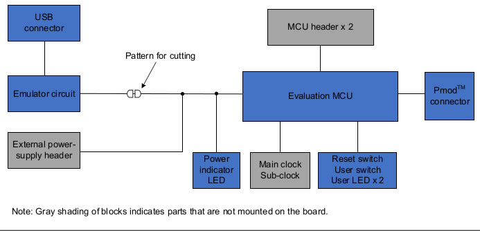
The board includes on-chip debugging, with a single USB cable for this and power.

Full access to all MCU pins is provided by through-hole header connections, along with a Pmod connector for ease of prototyping via the use of a wide array of third-party modules.

The board also includes a reset switch, plus a user switch and two user LEDs.

Development options
Applications can be developed using either e2 studio or CS+ (formerly CubeSuite+), although it is noted that the latter is not generally promoted to customers in the U.S. and Europe.
Alternatively, a standalone compiler package for the RX family may be installed, which will likely be of interest to those who prefer to use a third-party IDE or custom scripted builds etc.
e2 studio
Note that although e2 studio is available for Linux, the compiler for the RX device architecture is not and hence a Windows development system must be used.
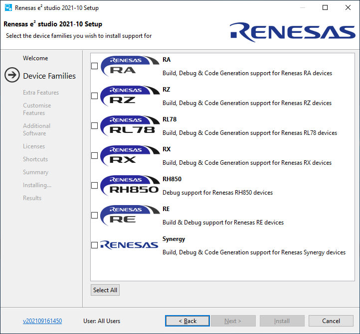
Upon running the installer we are prompted to select which devices we’d like to install support for.
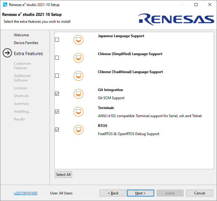
Next, we are prompted to select any extra features that we’d like to install, such as Git and FreeRTOS. We can then further customise these features in the next step.
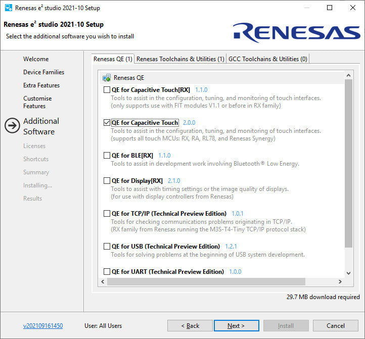
Following which we have the option of installing additional software, such as Quick and Effective (QE) Tools for particular applications, like capacitive touch, for example.
Now we can launch e2 studio and the first time this runs it will register the device support that we have installed.

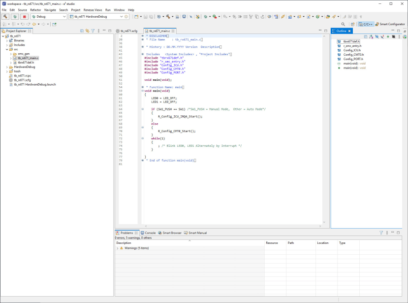
An LED Blink example program is available and this was downloaded via the RX671 Target Board web page, extracted and then imported into the IDE.
Upon attempting to build the example this resulted in an error due to the toolchain not being installed. However, this was easily remedied by downloading the latest RX family package – at the time of writing RX Family C/C++ Compiler Package V3 (without IDE) V3.03.00 – from the Upgrades section of the e2 studio web page.
Note that the IDE must be quit and restarted for it to detect a new toolchain and register this.

With the project successfully built, we can then proceed to launch the debugger and as we resume, sure enough, the two LEDs on the board next to the power LED start to blink alternately.
Comments