A First Look At The MAX20361 Evaluation Kit
Follow article
 Dave from DesignSpark
How do you feel about this article? Help us to provide better content for you.
Dave from DesignSpark
Thank you! Your feedback has been received.
Dave from DesignSpark
There was a problem submitting your feedback, please try again later.
Dave from DesignSpark
What do you think of this article?
The MAX20361 Evaluation Kit is the latest hardware offering from Maxim Integrated that combines MPPT solar cell harvesting techniques with a boost converter and adaptable charging capabilities. The board itself is designed with a high degree of hardware flexibility which supports input voltages from an onboard solar cell in addition to a choice of energy storage outputs including a lithium-ion cell or a supercapacitor.
The evaluation kit features an adaptor board that allows any developer direct access to the device over the I2C port using their computer. Maxim also includes a dedicated Graphical User Interface for Windows PC that significantly helps streamline the evaluation process and can be downloaded for free.
In this article, we will focus mainly on the GUI software to explore the key features of the evaluation kit and test the performance of the MAX20361 by observing the flow of power through the system.

Tools
- MAX20361 Evaluation Kit (210-5518)
- T3DSO1104 Digital Storage Oscilloscope (177-1267)
Testing and Observations
To evaluate the performance of the kit we first need to establish our testing setup by connecting the board to our computer. To do this, we first need to connect the USB2PMB2 adaptor and the USB cable that came with the kit to the board using the PMOD connector hardware provided. This will allow the MAX20361 to communicate with our computer over USB using the GUI software provided by Maxim.
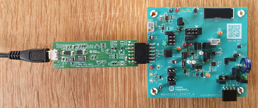
Connecting the USB2PMB2 adaptor and USB cable to a computer
As the MAX20361 uses the I2C protocol to communicate, we need the USB2PMB2 adaptor board to create a bridge between the evaluation kit and the USB port on our computer. However, the adaptor board does not provide direct power to the MAX20361 so we also need to connect the onboard solar cell to power the device using the jumper block provided.
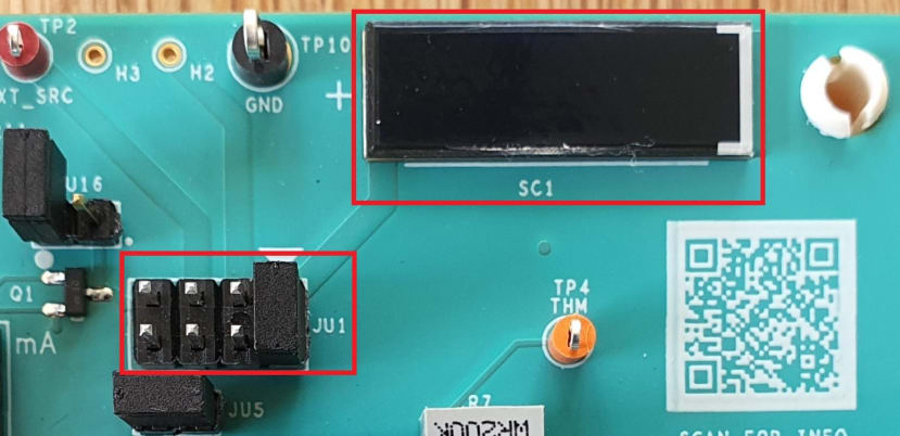
Use the jumper block to select the solar cell input
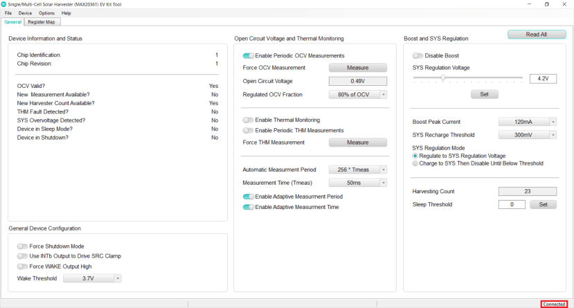
MAX20361 GUI showing the general tab and connected status
Exposing the board to a light source should give the MAX20361 enough power to establish a connection with our computer which should also prompt the GUI to update its connected status and start polling the device for register data automatically. The GUI software divides this data between two tabs that include a dashboard of key functions and a bitwise representation of all the MAX20361 registers that provide more specific details about the operation of the device.
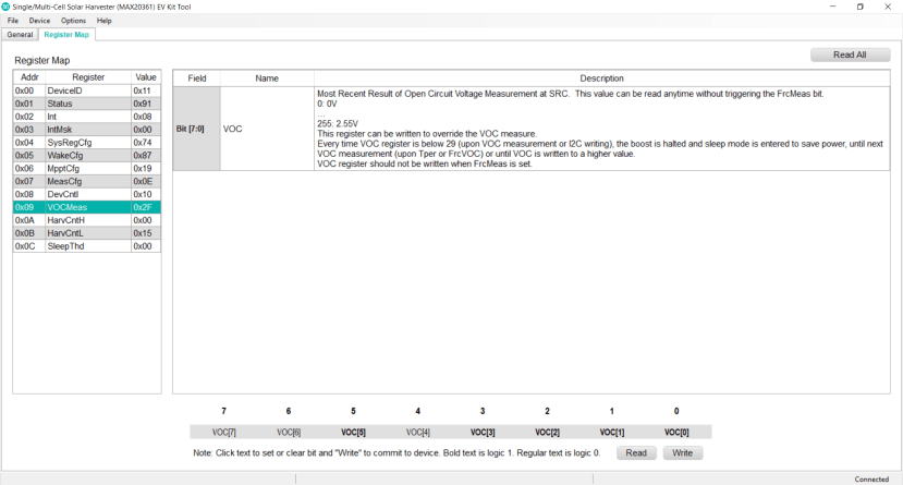
The MAX20361 GUI register map tab displaying bitwise value of open-circuit voltage measurement
The first function we need to evaluate is the open-circuit voltage measurement being taken from the output of the solar cell. This voltage input is measured periodically using a timer that can be manually configured for accuracy or responsiveness depending on the specific requirements of the system. This value not only gives an indication of the available light but also informs the operating characteristics of the harvesting process going forward.

MAX20361 GUI general tab showing open-circuit voltage and timing parameters
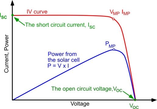
A typical maximum power point tracking (MPPT) curve used to monitor the yield of a solar cell
The MAX20361 uses the open-circuit voltage measurement to regulate the input source at an assumed maximum power point in the IV curve of the solar cell. This value can be fine-tuned by either using a known maximum power point and overwriting the MPPT configuration register, or tracking it manually using an external MCU and the harvest count register. The boost converter will then attempt to step the voltage up to a level that can either be used by an external device or stored for later consumption.

Use the jumper block to select the onboard supercapacitor
We will be using the onboard supercapacitor as our storage medium for this test which can be selected using the highlighted jumper block.
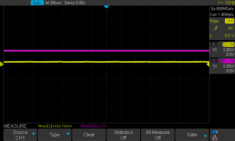
Oscilloscope reading of regulated solar cell input against charging supercapacitor output
The harvest count register is used to monitor the yield of the solar cell input between the open-circuit voltage measurements. This count records the number of boost cycles required to convert the input charge into the target output voltage and is proportional to the power generated. If this figure is below the sleep threshold register value the device enters sleep mode until the next voltage reading.

MAX20361 GUI displaying a high harvest count figure in direct sunlight
The harvest count can be used as a more accurate representation of true power yield from the solar cell and can actually vary significantly even with minor voltage fluctuations. Testing this parameter revealed that the difference in yield between direct and indirect sunlight was enormous, despite the perceived open circuit voltage change being relatively small. With this in mind, it was easy to boost the charging output voltage to almost 5v from a single solar cell!

Testing the limits of the solar cell and MAX20361 boost converter!
Once we have accumulated enough useable voltage in our chosen storage medium, the MAX20361 starts to compare this value against a minimum threshold. This level can be set by the developer and is used to enable dormant equipment connected to the MAX20361 using a dedicated wake output pin. This function has clearly been designed around the standard 3.7v lithium-ion cell which allows any connected devices to enter a low-power mode when the battery charge level drops too low.
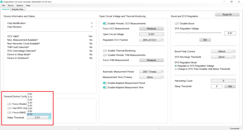
MAX20361 GUI displaying wake threshold drop-down options
The MAX20361 also features an upper voltage threshold that attempts to regulate the target output of the device and provide optimal charging conditions for a lithium-ion battery. The regulator features two recharging modes with flexible current control and a programmable lower recharge threshold that helps keeps the system charged anytime the sun is shining.
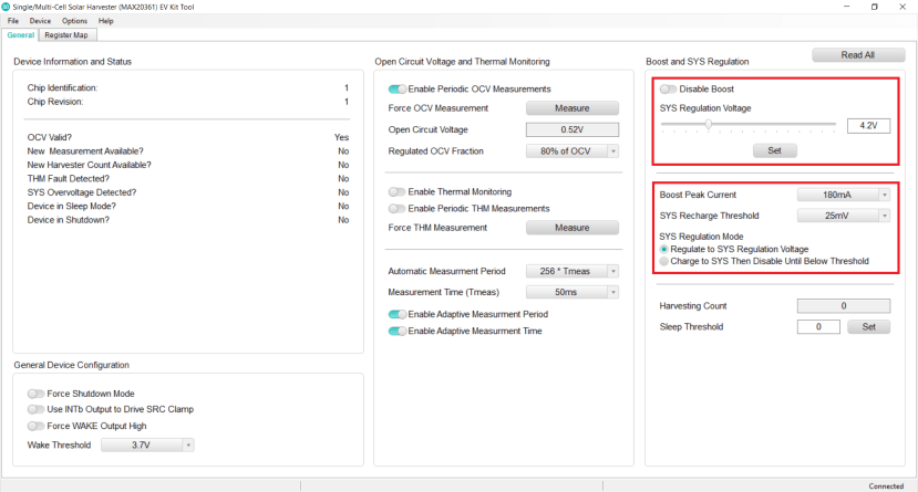
MAX20361 GUI displaying regulation voltage slider, peak current and recharge thresholds
Conclusion
The MAX20361 Evaluation Kit is an innovative platform that clearly demonstrates a broad scope for solar cell charge controllers in low-power and periodic-use applications. The super-low operating voltage and impressive boost capabilities allow the device to manage supercapacitors and single-cell lithium-ion batteries effortlessly which makes it very well suited to standalone 3v systems.
Maxim has also streamlined the development experience through their intuitive GUI software which is likely to encourage the uptake of the device while significantly reducing development times. Overall, the MAX20361 has demonstrated its potential for a broad range of applications and I am keen to see its use cases particularly in areas of wearables and IoT in the future.
Comments