A Comprehensive Look at Sources of Error in DC Voltage Measurements
Follow article
 Dave from DesignSpark
How do you feel about this article? Help us to provide better content for you.
Dave from DesignSpark
Thank you! Your feedback has been received.
Dave from DesignSpark
There was a problem submitting your feedback, please try again later.
Dave from DesignSpark
What do you think of this article?
In this post we will take a comprehensive look at all of the factors that can lead to errors in a DC voltage measurement with a DMM and how to eliminate them so you can achieve the highest accuracy possible in your measurement.
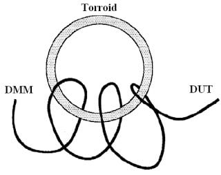
Radio Frequency Interference -- Most voltage-measuring instruments can generate false readings in the presence of large, high-frequency signal sources such as nearby radio and television transmitters, computer monitors, and cellular telephones. Especially when the high frequency energy is coupled to the multimeter on the system cabling. This effect can be severe when the cabling is 1/4, 1/2, or any integer multiple of the high frequency wavelength. You probably have experienced this type of effect first hand if you ever placed a mobile phone near speaker wiring and heard bursts of noise from the speaker that were certainly not part of the intended audio experience. To reduce interference, try to minimize the exposure of the system cabling to high-frequency RF sources. You can add shielding to the cabling or use shielded cabling. If the measurement is extremely sensitive to RFI radiating from the DMM or your DUT, use a common mode choke in the system cabling, as shown in the figure below, to attenuate DMM emissions. Often you can see this same EMI reducing method being used on the data cable for your computer monitor.
Thermal EMF Errors -- Thermoelectric voltages, the most common source of error in low level voltage measurements, are generated when circuit connections are made with dissimilar metals at different temperatures. Each metal-to-metal junction forms a thermocouple, which generates a voltage proportional to the junction temperature. It is a good idea to take the necessary precautions to minimize thermocouple voltages and temperature variations in low level voltage measurements. The best connections are formed using copper-to-copper crimped connections. The figure below shows common thermoelectric voltages for connections between dissimilar metals.
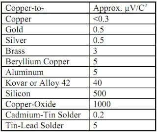
Keysight benchtop DMMs use copper alloy for their input connectors
Noise Caused by Magnetic Fields -- When you make measurements near magnetic fields, take precautionary steps to avoid inducing voltages in the measurement connections. Voltage can be induced by either movement of the input connection wiring in a fixed magnetic field, or by a varying magnetic field. An unshielded, poorly dressed input wire moving in the earth’s magnetic field can generate several millivolts. The varying magnetic field around the ac power line can also induce voltages up to several hundred millivolts. Be especially careful when working near conductors carrying large currents. Where possible, route cabling away from magnetic fields, which are commonly present around electric motors, generators, televisions and computer monitors. In addition, when you are operating near magnetic fields, be certain that the input wiring has proper strain relief and is tied down securely. Use twisted-pair connections to the multimeter to reduce the noise pickup loop area, or dress the wires as close together as possible.
Loading Errors Due to Input Resistance — Measurement loading errors occur when the resistance of the DUT is an appreciable percentage of the DMM’s own input resistance. The figure below shows this error source. To reduce the effects of loading errors, and to minimize noise pickup, see if your DMM allows you to set its input resistance to a higher value. For instance, using any of Keysight’s Truevolt DMMs such as 34460/61/65/70A, input resistance can be set from 10 M to > 10 G for the 100 mVdc, 1 Vdc, and 10 Vdc ranges.
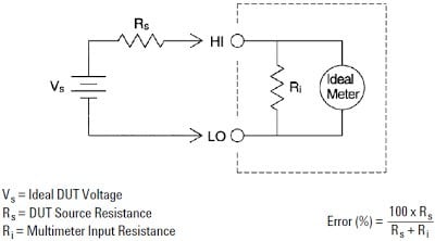
Ri should be much larger than Rs or loading error will be a factor in the measurement
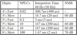
Power-Line Noise — This type of noise is caused by the powerline voltage signal (50 Hz or 60 Hz) being coupled onto the measurement setup either from the DUT, the DMM, or both. This noise appears as an AC ripple summed on top of the DC level you are measuring. To eliminate this common noise source DMM designers use integrating or averaging measurement time settings that are integer multiples of the powerline noise's period. Remember if you integrate over a sine wave you get zero. This is typically called normal mode rejection or NMR. If you set the integration time to an integer value of the powerline cycles (PLCs) of the spurious input, these errors (and their harmonics) will average out to approximately zero. For instance, the Keysight Truevolt DMM provides three integration times to reject power-line frequency noise (and power-line frequency harmonics). When you apply power to the DMM, it measures the power-line frequency (50 Hz or 60 Hz), and then determines the proper integration time. The table below shows the noise rejection achieved with various configurations. For better resolution and increased noise rejection, select a longer integration time.
Noise Caused by Injected Current — Residual capacitances in the DMM’s power transformer cause small currents to flow from the LO terminal to earth ground. The frequency of the injected current is the power line frequency or possibly harmonics of the power line frequency. The injected current is dependent upon the power line configuration and frequency. With Connection A (see figure below), the injected current flows from the earth connection provided by the circuit to the LO terminal of the DMM, adding no noise to the measurement. However, with Connection B, the injected current flows through the resistor R, thereby adding noise to the measurement. With Connection B, larger values of R will worsen the problem.
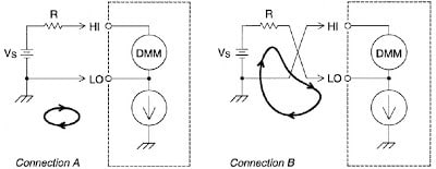
The measurement noise caused by injected current can be significantly reduced by setting the integration time of the DMM to 1 power line cycle (PLC) or greater.
If you think we missed anything or if you have a question, please leave it in a comment.
Comments