Building a Modular Synthesiser Part 5: A Multi-Function Module
Follow article
 Dave from DesignSpark
How do you feel about this article? Help us to provide better content for you.
Dave from DesignSpark
Thank you! Your feedback has been received.
Dave from DesignSpark
There was a problem submitting your feedback, please try again later.
Dave from DesignSpark
What do you think of this article?
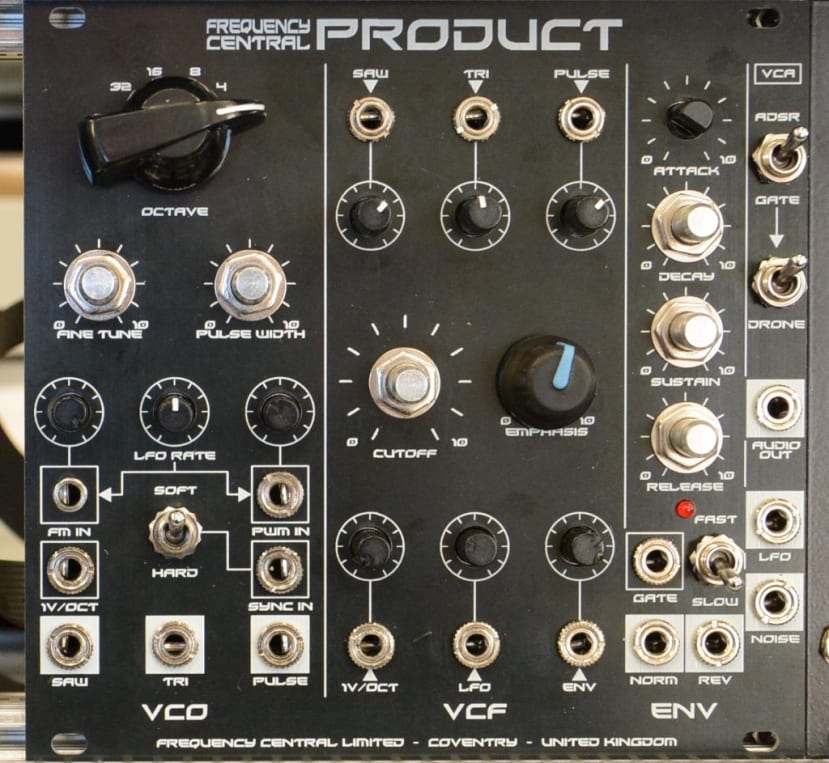
Assembling and testing the Frequency Central Product all-in-one synth module.
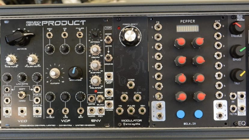
The Frequency Central Product is the biggest and most complicated of my synthesiser modules so far, comprising as it does of a Voltage Controlled Oscillator (VCO), a Voltage Controlled Filter (VCF) and an Attack, Decay, Sustain and Release (ADSR) all crammed into a 26hp Eurorack module.
As such, Product can be used as a standalone, fully-featured modular synthesiser that will also play nicely with the modules I have already built. It can also be used without patching, as each of its modules features pre-patched, normalised signal paths. All the pre-patched connections can be broken simply by inserting a jack into the relevant socket, hence it can easily be integrated with my existing modules.
A modular module
Product features a motherboard on which all pots, switches, and sockets are mounted and this is also where the pre-patched normalising happens.

To simplify the building process, there are three daughter boards that then plug into the Product motherboard:
- VCO daughterboard
- VCF/VCA daughterboard
- ADSR/noise daughterboard
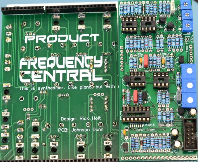
Resistors

Although the BOM did not indicate tolerance value for the resistors, I noticed in the pictures of the completed module that the resistors were all blue. I did a bit of research and found out blue resistors usually contain metal-oxide film elements, while the beige ones contain carbon film — although this does not appear to be a hard and fast rule. As I had blue ones I decided to use them to be consistent with the illustrations of the module.
The PCBs for this project have the actual values of the components printed on them, rather than a reference to the listing in the BOM, which meant that I didn’t need to keep referring back to this.
I have a Nova CB-14 resistor kit (156-2587) , which has all the resistors neatly filed away, which saved a lot of time locating the correct resistor and certainly helped this build go smoothly.
Motherboard

I started by building the motherboard. The instructions were fairly minimal, with just a suggested order for adding the parts to the PCB but the process was pretty straight forward. As with the other blog posts in this series, I have appended a BOM, the link to which is at the end of this article.
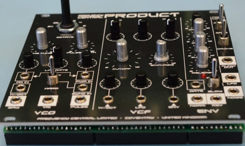
Once the smaller components were in place it was time to add the sockets, switches, and potentiometers. I wanted to make sure they all lined up correctly with the holes in the front panel, so I added them to the board without soldering and then fitted the panel, holding it in place by adding the nuts to some of the potentiometers. I could then turn the whole thing over and solder everything in place.
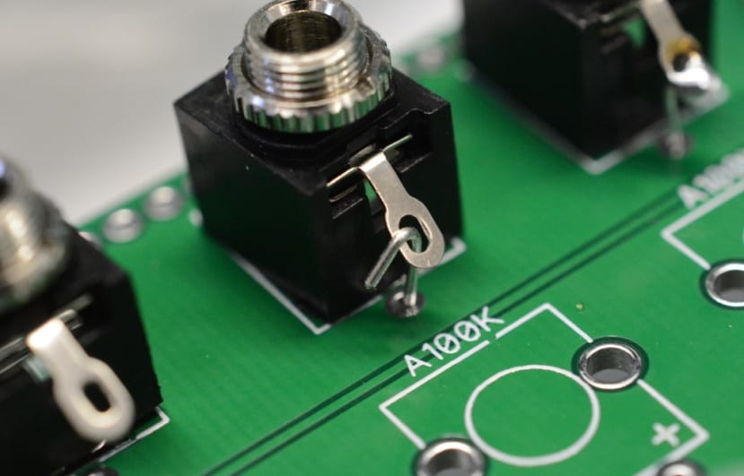
Following which I had to remove the front panel to ground the sockets to the PCB using cut off resistor legs which proved to be quite a fiddly task. I then followed a similar procedure to get the LED lined up correctly.
Finally, I cut seven female headers to size. They are fitted to the other side of the PCB and I held each one in place with blu tack while it was being soldered, checking it was straight and at right angles to the board after soldering one leg, before doing the rest. It was important these were all correctly lined up, since this is where the daughterboards would plug in, so if they were out of alignment it could make life tricky when they were being added.
I then needed to put together the rotary switch PCB. This features a 1P12T
(066-5180)
rotary switch that will set the octave of the oscillators. It needs to be configured to be a 6-position switch rather than 12. This is done by removing the mounting nut and the washer, to reveal another washer with a small flange that fits into one of the slots around the shaft. To make a 6-position switch, simply fit the washer so the flange is in the slot marked “6”. Test the switch to make sure you’re getting 6 positions and then replace the mounting nut and washer to keep it in place while you solder the switch to the PCB.

The other thing I needed to do for the Octave PCB was sort out five matched 10k resistors. Apparently they didn’t need to be exactly 10k as long as they were all the same, so I tested a bunch until I had 5 the same value. Having done that and soldered them in place I remembered I had ordered 5 resistors with 1% tolerance (830-7466) specifically to use here and had forgotten all about them! I am sure they will come in handy for a future project.
VCO

Next was the VCO daughterboard, which went together in a similar fashion to the motherboard.
To make absolutely certain that the headers for connecting it to the motherboard were correctly aligned, after cutting them to the correct size I added them to the appropriate female headers on the motherboard and then fitted the VCO board in place before soldering them.
Once the VCO was complete and plugged into the motherboard, I could power the module up and calibrate the rotary octave switch. There is a test point next to it that should give 7.5V, as marked when the octave switch is in its highest position. I adjusted the trimmer until I could see a 7.5V output on my meter.

VCF/VCA and ADSR

These two boards went together without any problems; I took extra care to get all the diodes and polarised capacitors the right way around. Also ensuring that the transistors were in the correct locations, as well as the correct orientation. An “n” marked on the board indicates an NPN BC547 transistor and a “p” indicates a PNP BC557 transistor. The orientation is shown by the half circles.
Although the VCF/VCA board has space for a power connector, that is not needed as it takes power from the motherboard.
I initially missed a diode off the ADSR board – but that was soon fixed.

Finishing touches
I always end up learning new stuff when building things like this. Apart from the thing about the colour of the body of resistors that I mentioned above, I also learned that there are two types of potentiometer knobs to fit D shafts. One with the flat part of the D on the same side as the indicator line and one with it on the opposite side. I needed the latter type which are not quite so easy to find. I only need 2 but I would like them to match the knobs for the round shaft pots (they would also be an improvement on the ones I have on the Bella Pepper module at the moment) – so the search is on!
In the meantime this module works well as you can hear:
It also integrates well with my other modules:
To help me get a better understanding of how everything is working I intend to hook up my oscilloscope and monitor different points in various patches to see how things are interacting.
My only problem now is that my rack is full and a keep discovering new modules I want to try out!
Parts available in this series: