How Does a Bridge Rectifier Convert AC to DC? Equations Explained
Follow article
 Dave from DesignSpark
How do you feel about this article? Help us to provide better content for you.
Dave from DesignSpark
Thank you! Your feedback has been received.
Dave from DesignSpark
There was a problem submitting your feedback, please try again later.
Dave from DesignSpark
What do you think of this article?
1 What Bridge Rectifier Do?
Bridge Rectifier converts the alternating current generated by the alternator into direct current to supply power to electrical equipment and components.
The bridge rectifier circuit uses the unidirectional conductivity of the diodes, divides the four diodes into two groups, and conducts respectively according to the polarity of the transformer secondary voltage, and connects the positive terminal of the transformer secondary voltage to the upper terminal of the load resistance, the negative terminal is connected to the lower end of the load resistance, so that a unidirectional pulsating voltage can always be obtained on the load.
Bridge rectifier circuit is powerful. For example, charge the storage battery. Limit the battery current to flow back to the generator to protect the generator from being burnt out by the reverse current.
2 What Bridge Rectifier Consist of?
2.1 How Does Bridge Rectifier Work?
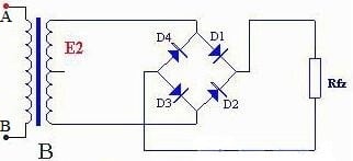
Figure 1. Typical Bridge Rectifier Circuit
In the positive half cycle, D1 and D3 are on, D2 and D4 are off.
In the negative half cycle of u2, D1 and D3 are off, and D2 and D4 are on.
It is not difficult to see from the Figure 1 that the reverse voltage of each diode in this bridge circuit is equal to the maximum value of the secondary voltage of the transformer, which is half smaller than the full-wave rectifier circuit. So bridge rectifier is an improvement on diode half-wave rectifier.
2.2 How to Calculate Bridge Rectifier
The main parameters of bridge rectifier circuit calculation.

3 Why Bridge Rectifier is Powerful?
The bridge rectifier circuit overcomes the shortcomings that the full-wave rectifier circuit requires the transformer secondary to have a center tap and the diode have to withstand large back pressure, but two more diodes are used. With the rapid development of semiconductor devices and low cost today, bridge rectifier circuits are widely used in practice.
It needs to be pointed out that the diode as a rectifier component should be selected according to different rectification methods and load requirements. If you choose improperly, you may not be able to work safely, or even burn the diodes.

4 How Bridge Rectifier Converts AC to DC?
To simplify, the diode is treated with an ideal model, that is, the forward conduction resistance is zero and the reverse resistance is infinite. The bridge rectifier circuit can also be considered as a kind of full-wave rectifier circuit. The transformer windings are connected to four diodes according to the method above. D1 ~ D4 are four identical rectifier diodes connected in the form of a bridge, so they are called bridge rectifier circuits. Using the guiding function of the diode, the secondary output can be directed to the load even in the negative half cycle. The specific connection method is shown in the figure. It can be seen from the figure that in the positive half cycle, the current is guided by D1 and D3 to pass through RL from top to bottom, and in the negative half cycle, the current flows by D2 and D4 to pass through RL from top to bottom. To achieve full-wave rectification, in this structure, if the same DC voltage is output, the secondary winding of the transformer needs only half of the winding compared with full-wave rectification. However, if the same current is to be output, the wire diameter of the winding should be thickened accordingly. As for the pulsation, it is exactly the same as the full-wave rectifier circuit.
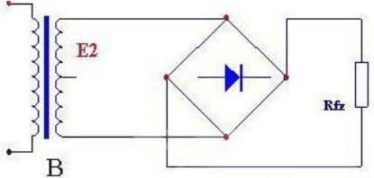
Figure 2. Simplified Bridge Rectifier Circuit
The advantages of the bridge rectifier circuit are that the output voltage is high, the ripple voltage is small, and the maximum reverse voltage that the tube can withstand is low. At the same time, because the power transformer has current supply to the load in the positive and negative half cycles, the power transformer is fully utilized.
Because the output voltage of the rectifier circuit contains larger pulsating components, in order to reduce it as much as possible, there is necessary to keep the DC component as much as possible to make the output voltage close to the ideal DC. This measure is filtering. Filtering is usually achieved by using the energy storage effect of capacitors or inductors.
5 Parts of Bridge Rectifiers
5.1 Inductor Filtering
The inductor filtering circuit uses the characteristic that the current at both ends of the inductor can not change suddenly. Connect the inductor and the load in series to achieve the purpose of smoothing the output current. From the energy point of view, when the current provided by the power supply increases (caused by an increase in the power supply voltage), the inductor L stores energy; when the current decreases, the energy is released to smooth the load current, so the inductor L has a smoothing effect.

Figure 3. Inductor Filtering Circuit
Advantages: the conduction angle of the rectifier diode is large, the peak current is small, and the output characteristics are relatively flat.
Disadvantages: There is an iron core, which is heavy and bulky, causing electromagnetic interference. However, it is only suitable for low voltage and high current occasions.
5.2 Capacitor Filtering
Capacitor filtering circuit is to connect a large capacity capacitor in parallel with the load in rectifier circuit. Due to the charging and discharging effect of the capacitor and the existence of the voltage across the capacitor, the pulsation degree of the output voltage UL of the rectifier circuit is greatly reduced, and the waveform is nearly smooth, which plays a role of filtering.
The filter output voltage waveform of the bridge rectifier capacitor is shown in Figure 4 (actually the filtered output waveform). In this capacitor filter circuit, the larger the capacitance of the capacitor or the larger the load resistance, the slower the discharge of the capacitor and the smoother the output voltage. In addition, the pulsation component decreases and the average value of the output voltage increases.
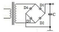
Figure 4. Capacitor FilteringCircuit
It is important to note that due to the voltage effect of the filter capacitor, the diode conduction of the single-phase capacitive input rectifier filter circuit is no longer a complete half cycle of conduction, but a narrow pulse, which makes the parameter selection of the rectifier diode and the rectifier circuit of the inductive input very different.
5.3 Compound Filtering
The compound filter is a filtering circuit that has a combination of inductor-capacitor or resistor-capacitor form. The working principle is the same as that of single capacitor filter and inductance filter, except that the output waveform is smoother and the load is almost equal to dry battery power supply voltage.
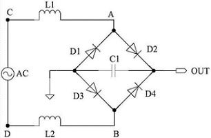
Figure 5. Compound Filtering Circuit
6 Bridge Rectifier Calculation
6.1) Peak Current
The peak current through the load, if the diode has a forward resistance, then
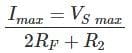
Here, we get twice the forward resistance. Assuming that all diodes have the same forward resistance, then two diodes are used for a half cycle, and the two forward resistances can be expressed in the formula.
6.2) Output Current

Where, Idc is the current flowing through the load and Im is the peak of the ac current.
6.3) DC Output Voltage
Where, Vdc is the output DC voltage, Idc is the DC current flowing through the circuit, and R is the load connected to the circuit.
6.4) RMS Output Current
6.5) Form Factor
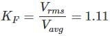
Where, the Vavg is the average or the DC voltage
6.6) Output Frequency
Where, fout is the output frequency and fin is the input or power supply frequency.
6.7) Rectification frequency
6.8) Ripple Factor

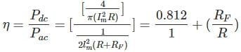
6.9) Transformer Utilization Rate

7 Failure Analysis of Positive Half Cycle Bridge Rectifier Circuits
| Open Circuit | Failure | Analysis |
|---|---|---|
| The ground wire is open. | No DC voltage output | The current of the bridge rectifier diode in the circuit cannot form a loop, and the circuit cannot work. |
| One diode is open. | Unidirectional pulsating DC voltage drop | The positive or negative half cycle of the AC input voltage is not rectified into a unidirectional pulsating DC voltage. |
| Two diodes with different sides open simultaneously. | No output voltage | Neither the positive half cycle nor the negative half cycle of the AC input voltage is rectified into a unidirectional pulsating DC voltage, and the output voltage is 0V. |